Final project
Introduction
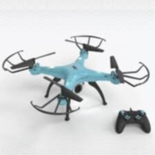
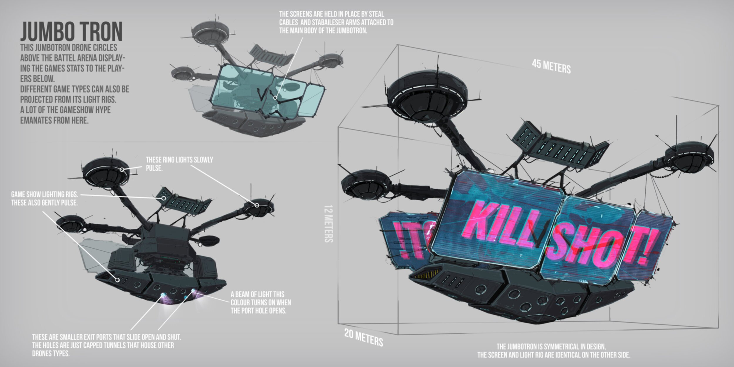
I wanted to combine 2 random objects that interest me into one project. A drone and a jumbotron. So im gonna make a drone with multiple screens on it that could for example be used for traffic control or entertainment purposes. There is no real reason why I chose to make this beside it looking and sounding fun to design and build.
What does the drone do?
The drone needs to be able to fly for at least 20 minutes. It needs 2 screens on both side so it can display images or video. I wanna program the drone myself so I know how drones work and how they keep themselves upright.
Drone
basic requirements
- 2 screens
- Speakers
- 20 min flight time
- custom micro controller pcb that controls the drones and screens
- 50 meter range from controller
Sensors
- GPS
- IMU/rotation sensor
- Read voltage from battery know battery percentage
Requirements when far ahead
- Docking station
- Automatic docking
- Automatic pathing
- Design own electronic speed controllers
Images

Drawing the drone
I have a few concept images above and this is the result my drawings.
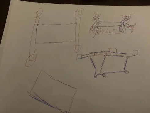
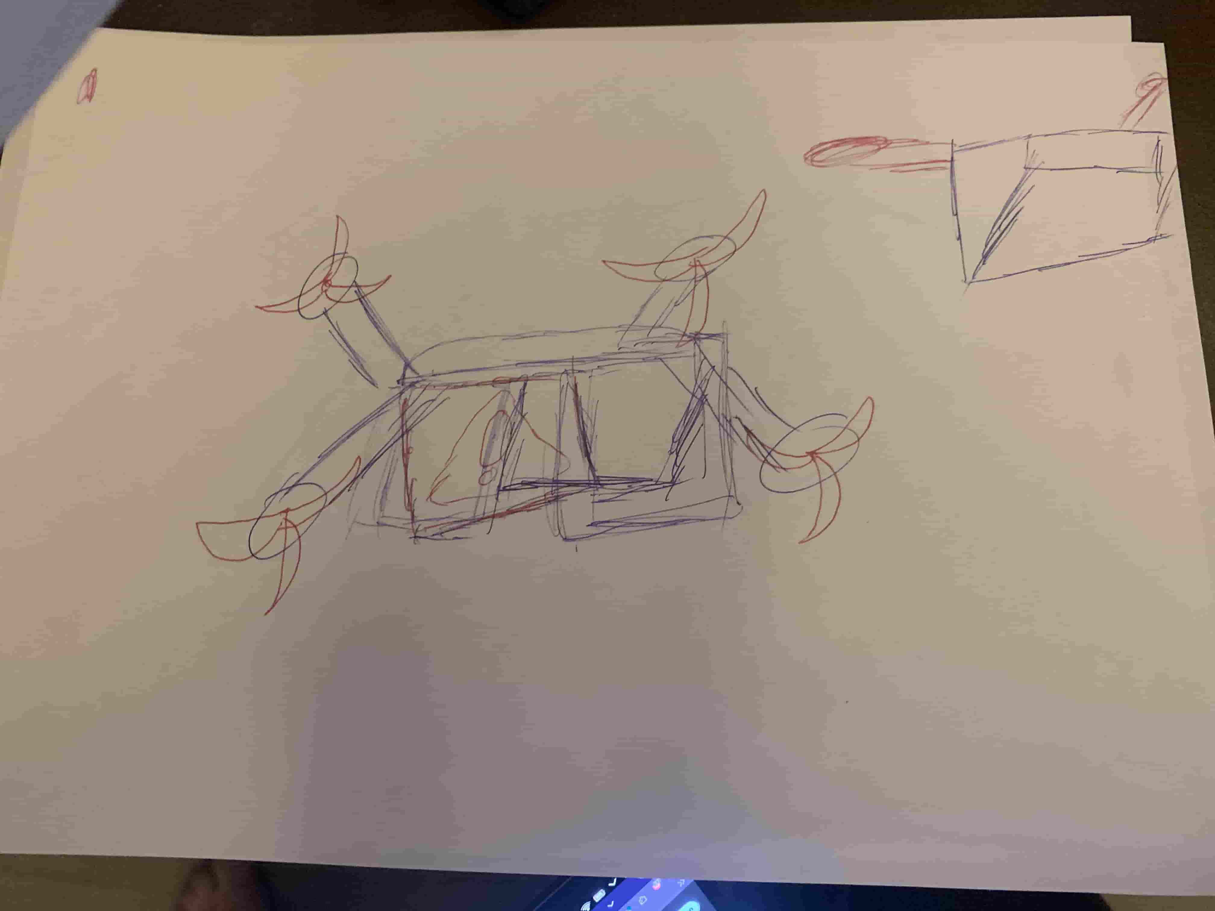
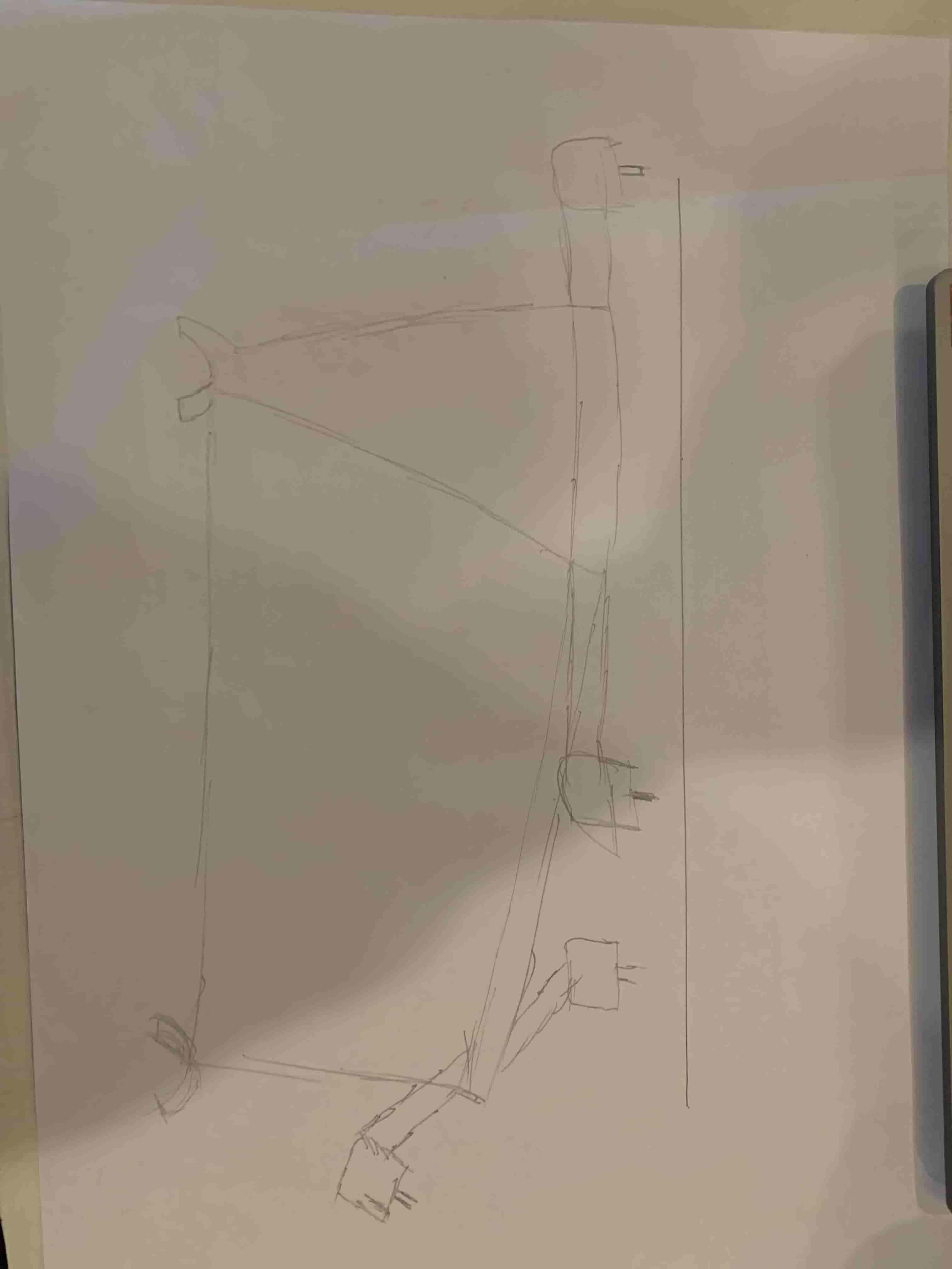
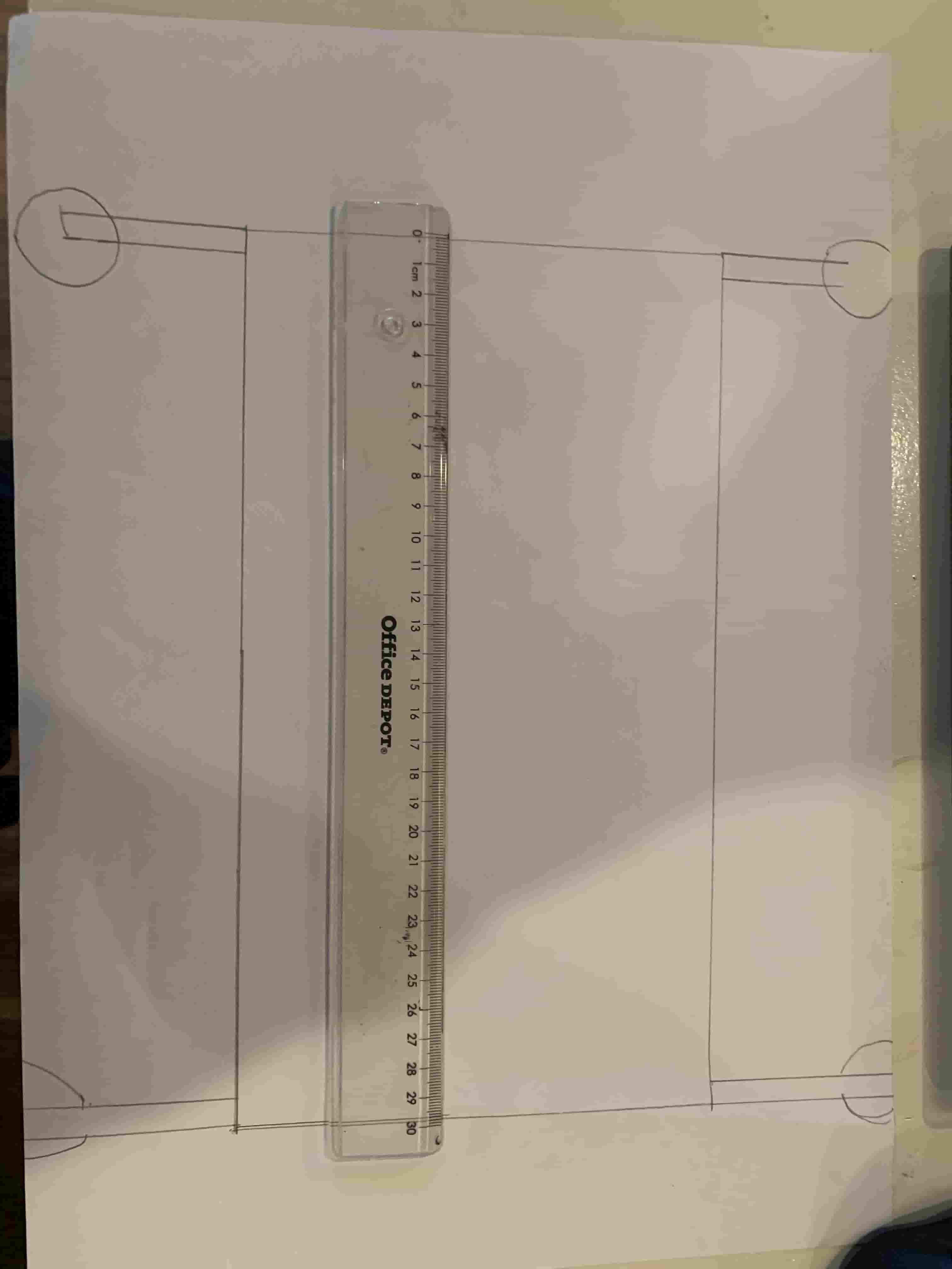
In the second picture you can see that I wanted to make the drone 30 cm in length. But then I looked at the prices for bigger batteries and it started to get super expansive real fast. So I decided to make it smaller. So now im planning on making a drone 10 cm in length. Im still going for the design in the third image. You can also kinda see that I got my inspiration from the third concept art image. And im giving my on twist on it.
Designing the drone
When designing the drone I wanted to do everything parametric. So im going to try to use as much variables as possible and make everything depend on each other so everything automatically scales when I change one parameter.
Designing the drone parametrically
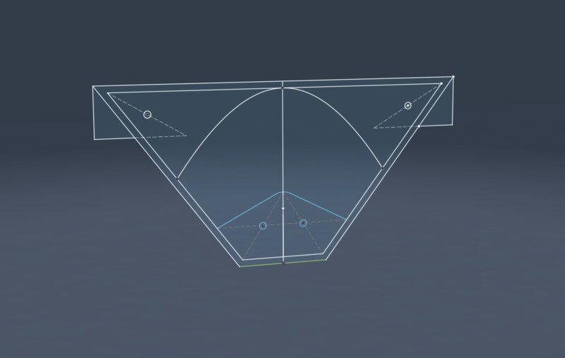
Designing parametrically is very hard because every constraint needs to be perfect. Otherwise when changing lengths the design will fold into itself like this.
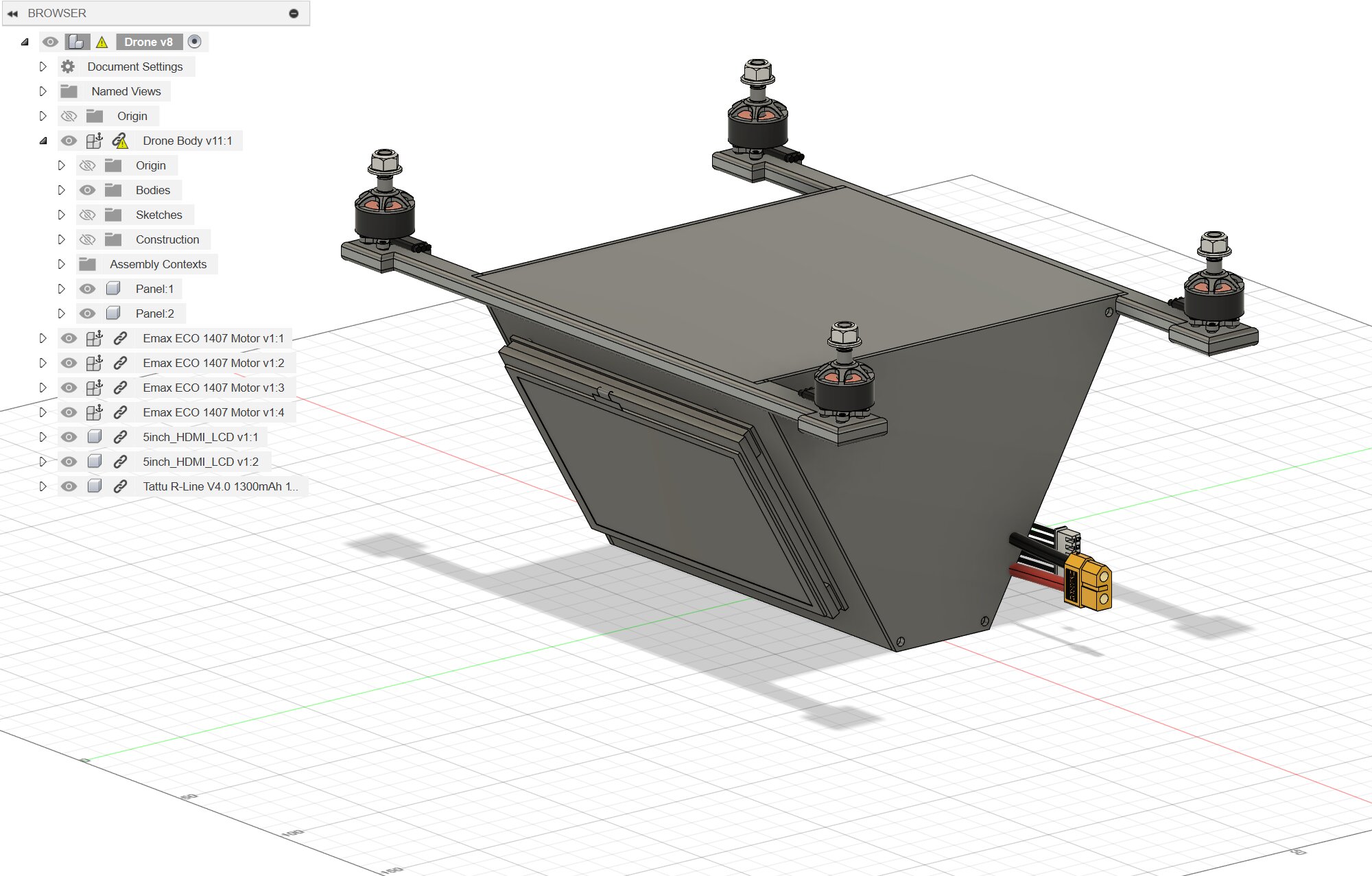
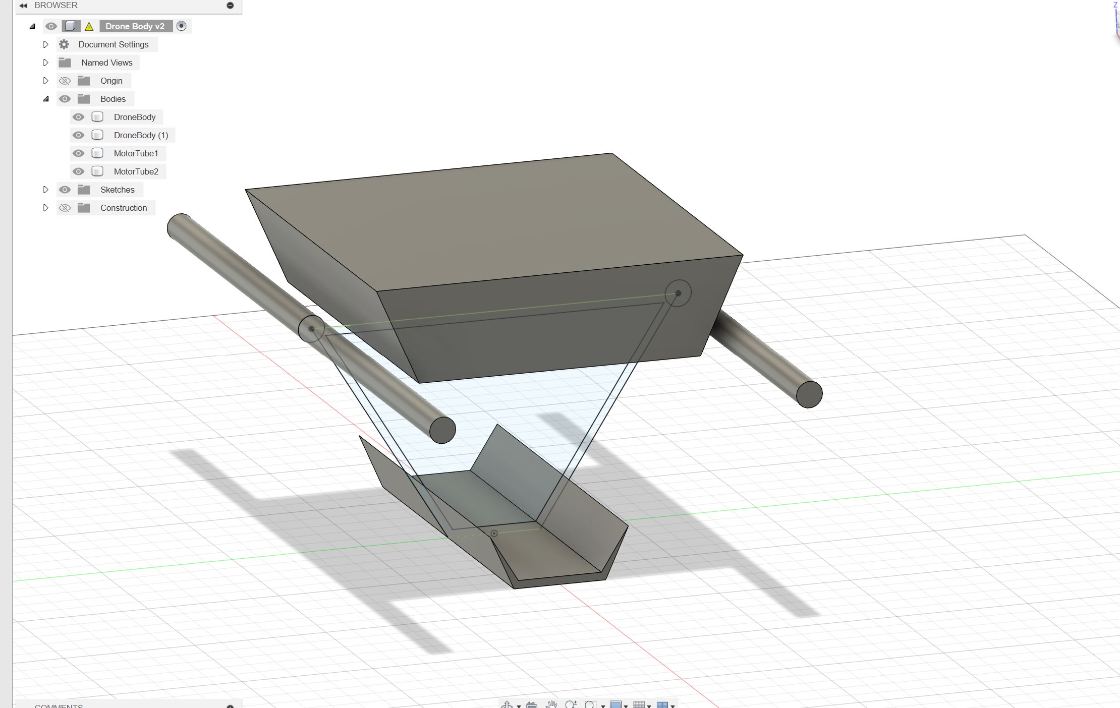 I've spend one day getting the constraints perfect for the sketch so it scales well with everything. And this is the result of that. When I change one parameter in the variable menu the entire body scales with it. This is the final result of my design. I've made the body myself and I've imported the components from GrabCad. So I had more time for blender and Onshape and so I could visualize it better.
Rendering
I've also made a render of the drone to visualize it for other people. Making this was kind of a pain because blender is a gigantic program. You can see my docs to see where I struggled. This is my final result of the render. I've wished it looked nicer but I didn't have enough time to dive deeper into blender.
Feedback from Bas and Henk
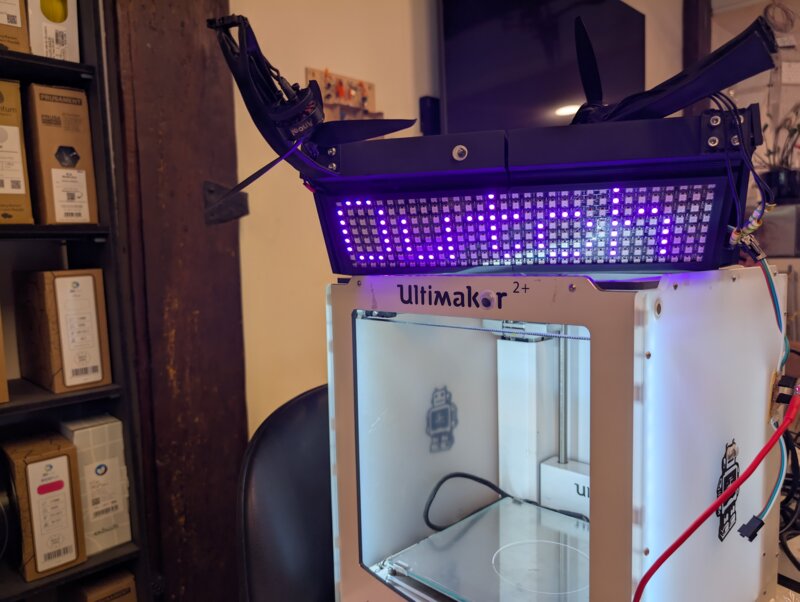
I've gotten some feedback on my design and about the use of screens. Maybe I should only use speakers or use LED matrixes. After thinking about it I think im going to give LED matrixes a spin.
Drone electronics
For the drone I will need a lot of electronics. But I will also need a pcb for inside the drone so I don't have any loose connections. The main board needs a couple of components. Something to step down the voltage from the big battery or I will use two separate batteries one for the motors one for the control board. I will also need a sensor to know the position of the drone and a micro controller. I also need a lot of power to power the screens so that will also be something interesting.
Components
- MCU
- BNO085
- Something to drive the LED matrixes
- SD card/ secondary MCU to control the matrixes
- LED (mandatory)
Drone remote electronics
I'm also building the remote for the drone
- Potentiometer slider for the throttle
- Joystick for left-right-forward-backwards
- battery
- screen to see status of drone
- LED (mandatory)
Joystick
I really wanna use a joystick for this project because having 2 potentiometers under each other looks a bit weird.
KiCad
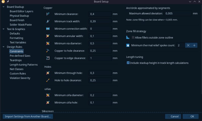
The first thing I did was import the design rules for our milling machine. I used the file from the lecture to import it from because there we set everything up together.
Now im going to grab all the components needed for the board * Joystick x2 * LED * small oled screen * xiao espS3
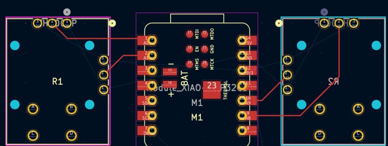
I was struggling a lot when thinking on how to connect the joysticks because the data sheet says it needs 5 volts. Until I realized they where potentiometers and they should work with any voltage. So I could directly connect the Joysticks to the MCU
Instead of it looking like this.
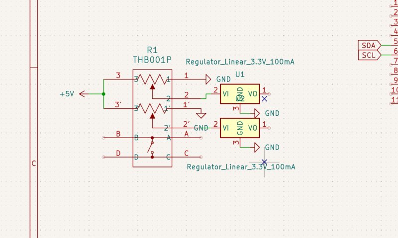 This configuration wouldn't have worked anyway because the voltage regulator forces the voltage to 3.3 so the mcu will only read one value.
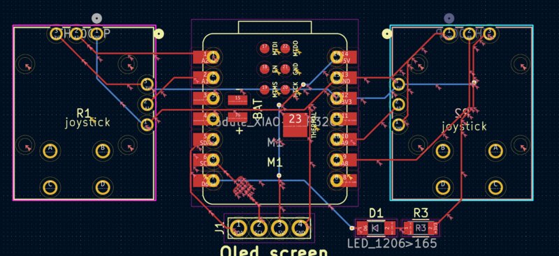
It now looks like this:
This configuration wouldn't have worked anyway because the voltage regulator forces the voltage to 3.3 so the mcu will only read one value.
It now looks like this:
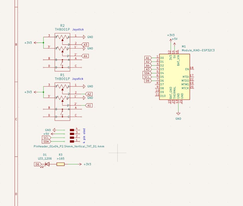 So I have 2 joysticks that are directly connected to the mcu. A screen that works on the I2C protocol and a LED.
First when routing the joysticks I realized that the Xiao has analog on both sides of the board. So if I change the schematic so it connects to the other side I have a lot less longer traces.
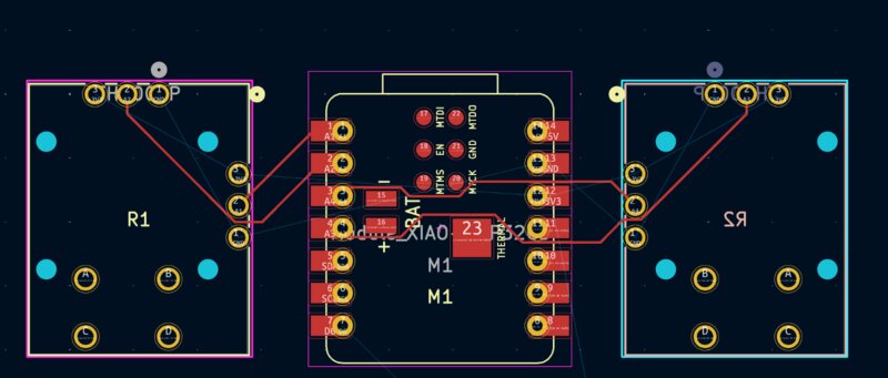
 So like this instead of needing them to go across the entire mcu.
I forgot to apply the design rules so I imported them again and now I have to retrace everything. Thanks Irja for checking them together.
Then I needed to draw the outlines. To draw curved lines I used this tutorial. It's hard to get the get everything symmetrical. Maybe there is already a tool to do that but I don't know where to find it.
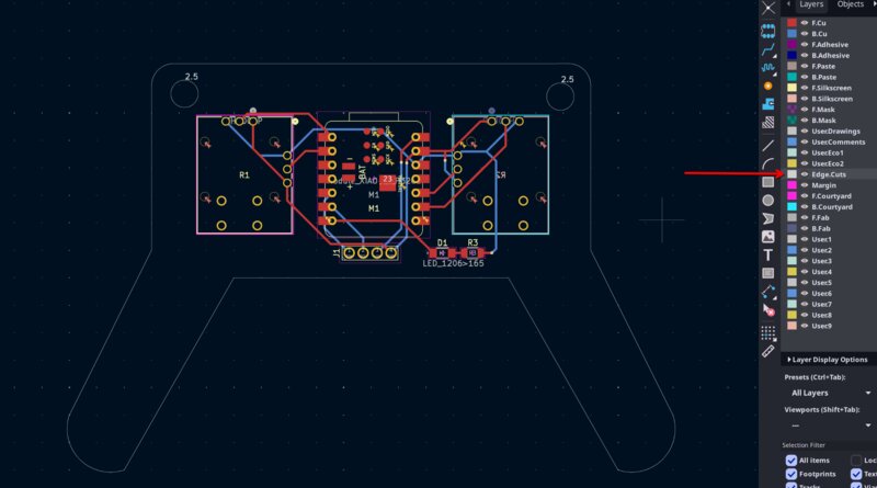
This is the result of the board.
After some weeks I changed the design to this. Because I noticed the esp-C3 doesn't have enough analog pins for my joysticks so I asked Henk if I could use one of their esp-S3's because it had a lot more analog pins.
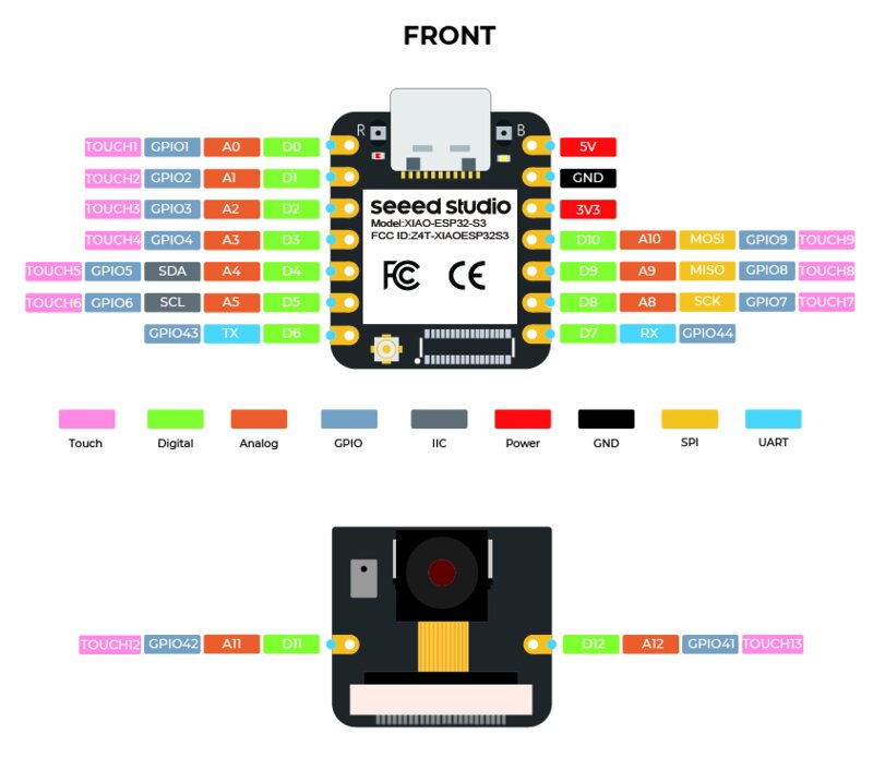 ESP S3
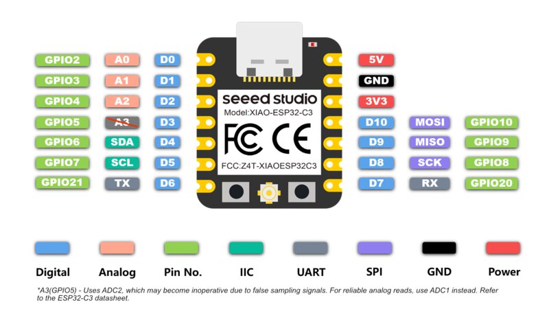 ESP C3
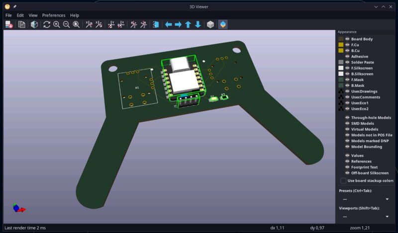
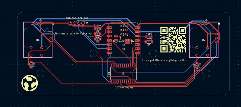 New design
This new design also saves a lot on material because the legs don't have to be cut out so I can almost make twice as many boards with the same material.
New design
This new design also saves a lot on material because the legs don't have to be cut out so I can almost make twice as many boards with the same material.
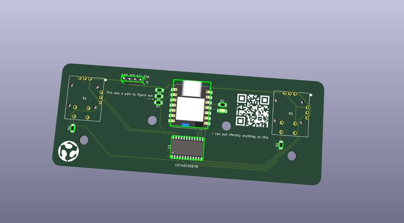
I've also send this board to JLCPCB for FR04 fabrication. Because I had issues where my FR-1 copper would just let got when moving the joysticks around. I wanted the controller to be super reliable and durable so that's why I ordered them from JLCPCB
Programming
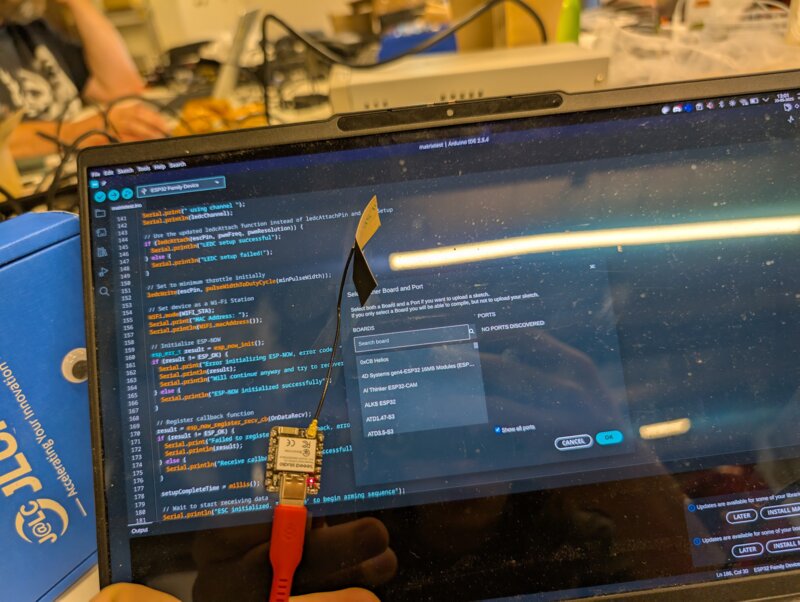
For the drone I will be using the dRehmFlight VTOL program. In the programming week I already modified it to support the BNO085 and made the bridge between my handheld controller and the flight controller using ESPNow. For further support I still had some bugs to squash and some other features to implement for compatibility with my system.
classDiagram
namespace Drone {
    class ESPC6{
        +Control Motors
        +keep drone in the air
        +Receive communication from controller
        Flightcontroller()
    }
    class MatrixControllerRP2040 {
        +Receive communication from ESPC6 for Matrix data
        ShowMatrix()

    }

}

namespace Controller {
    class ESPC3 {
        +Read joystick data
        +Clean joystick data
        +Send joystick data to the drone
        Handheld Controller()
    }
}

ESPC3 --> ESPC6 : Send data to flight controller using ESPNOW
ESPC6 --> MatrixControllerRP2040 : Serial communication
I have already gotten the motors to spin in week 10 using the script in there. Now I also need to modify the original VTOL driver so my ESC's can properly understand it's instructions.
There's one specific function I need to change.
Old
void commandMotors()
{
// DESCRIPTION: Send pulses to motor pins, oneshot125 protocol
/*
* My crude implementation of OneShot125 protocol which sends 125 - 250us pulses to the ESCs (mXPin). The pulse lengths being
* sent are mX_command_PWM, computed in scaleCommands(). This may be replaced by something more efficient in the future.
*/
int wentLow = 0;
int pulseStart, timer;
int flagM1 = 0;
int flagM2 = 0;
int flagM3 = 0;
int flagM4 = 0;
int flagM5 = 0;
int flagM6 = 0;

// Write all motor pins high
digitalWrite(m1Pin, HIGH);
digitalWrite(m2Pin, HIGH);
digitalWrite(m3Pin, HIGH);
digitalWrite(m4Pin, HIGH);
digitalWrite(m5Pin, HIGH);
digitalWrite(m6Pin, HIGH);
pulseStart = micros();

// Write each motor pin low as correct pulse length is reached
while (wentLow < 6)
{ // Keep going until final (6th) pulse is finished, then done
    timer = micros();
    if ((m1_command_PWM <= timer - pulseStart) && (flagM1 == 0))
    {
    digitalWrite(m1Pin, LOW);
    wentLow = wentLow + 1;
    flagM1 = 1;
    }
    if ((m2_command_PWM <= timer - pulseStart) && (flagM2 == 0))
    {
    digitalWrite(m2Pin, LOW);
    wentLow = wentLow + 1;
    flagM2 = 1;
    }
    if ((m3_command_PWM <= timer - pulseStart) && (flagM3 == 0))
    {
    digitalWrite(m3Pin, LOW);
    wentLow = wentLow + 1;
    flagM3 = 1;
    }
    if ((m4_command_PWM <= timer - pulseStart) && (flagM4 == 0))
    {
    digitalWrite(m4Pin, LOW);
    wentLow = wentLow + 1;
    flagM4 = 1;
    }
    if ((m5_command_PWM <= timer - pulseStart) && (flagM5 == 0))
    {
    digitalWrite(m5Pin, LOW);
    wentLow = wentLow + 1;
    flagM5 = 1;
    }
    if ((m6_command_PWM <= timer - pulseStart) && (flagM6 == 0))
    {
    digitalWrite(m6Pin, LOW);
    wentLow = wentLow + 1;
    flagM6 = 1;
    }
}
}
What this function does is generate PWM values in software which is super inefficient. The esp32C6 according to it's datasheet supports 6 separate PWM clocks in hardware.
 So I wanna use these to reduce the overhead and so the loop doesn't have to run 20 times a second but faster making the drone respond faster. To use these I need to use this library.
Right link: https://docs.espressif.com/projects/arduino-esp32/en/latest/api/ledc.html
So I wanna use these to reduce the overhead and so the loop doesn't have to run 20 times a second but faster making the drone respond faster. To use these I need to use this library.
Right link: https://docs.espressif.com/projects/arduino-esp32/en/latest/api/ledc.html
When first looking at the documentation I got super confused why nothing was working but that was because I was looking at the documentation for the wrong framework. I was looking at the ESP-IDF framework instead of the Arduino framework. Wrong link: https://docs.espressif.com/projects/esp-idf/en/stable/esp32/api-reference/peripherals/ledc.html
So I really needed 2 functions of the library. * To set pwm channel, pin and resolution (ledcAttach) * To set the PWM frequency (ledcWrite)
Generative design
Online I saw a lot of organic designs that where created by generative design.
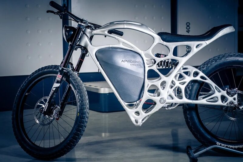 Credits: FormLabs
I wanted to do this myself for the drone arms. So I started messing around in the generative design tab of my drone arm model.
Credits: FormLabs
I wanted to do this myself for the drone arms. So I started messing around in the generative design tab of my drone arm model.
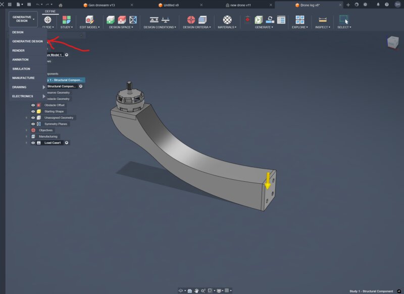 I've already designed the base of the arm. What generative design does is either add or remove material based on parameters you give it.
I've already prepared my model by created some parts as separate bodies. So I can preserve them during the generation process.
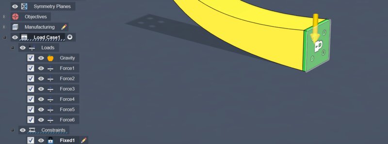
When creating a Study you need to assign which parts to groups.
I've already designed the base of the arm. What generative design does is either add or remove material based on parameters you give it.
I've already prepared my model by created some parts as separate bodies. So I can preserve them during the generation process.
When creating a Study you need to assign which parts to groups.
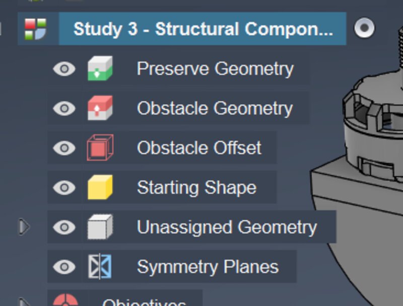 * The preserve Geometry group where loads get applied
* Obstacle Geometry gets avoided and no loads get placed on there.
* Obstacle offset increases the size of a body by an x amount of mm.
* Starting shape is the group that is mainly going to get modified
* Unsigned geometry are bodies that are not assigned yet
* symmetry planes are a way to define a plane where both sides need to be mirrored (symmetrical)
* The preserve Geometry group where loads get applied
* Obstacle Geometry gets avoided and no loads get placed on there.
* Obstacle offset increases the size of a body by an x amount of mm.
* Starting shape is the group that is mainly going to get modified
* Unsigned geometry are bodies that are not assigned yet
* symmetry planes are a way to define a plane where both sides need to be mirrored (symmetrical)
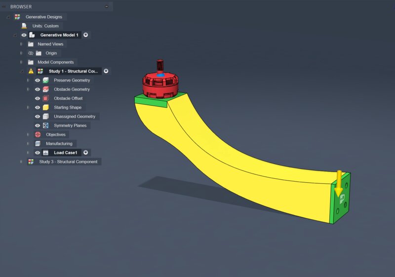
So after assigning everything this is my result.
After that you can open the Objectives tab to see what you wanna do and set more limits.
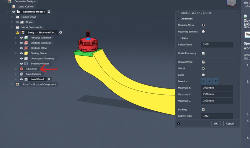
The only things I understand from this menu is the Objectives and the Displacement. The objective is straight forward and the Displacement is the amount of millimeters it is allowed to fluctuate from the original design in said direction.
Now it's time to add the loads on the part. So the amount weight and force the part needs to be able to handle.
For that there's a keybind L
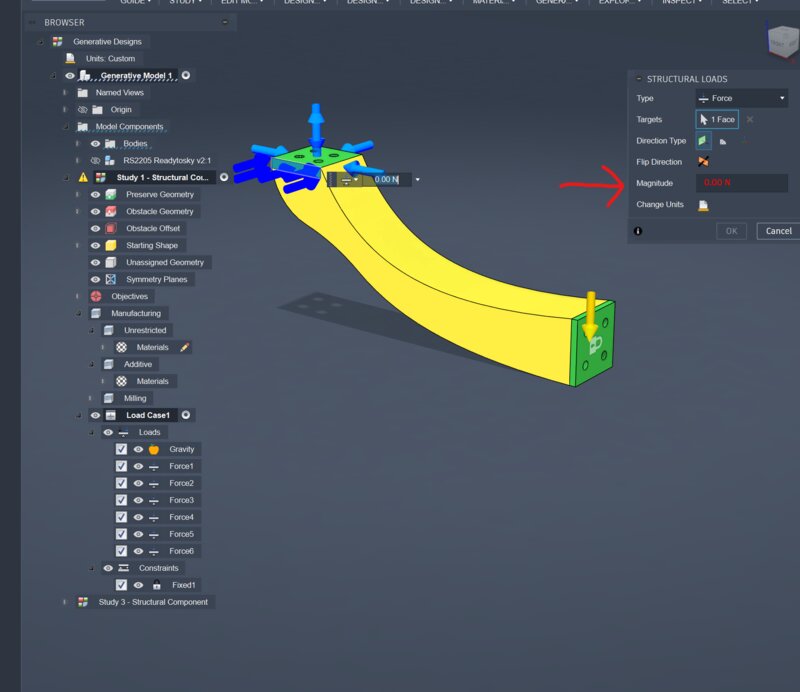 After you've pressed that you can click a face and add force to it. In my instance it needs to withstand at least 2 kg in all directions.
The formula for Kg to Newton is.
After you've pressed that you can click a face and add force to it. In my instance it needs to withstand at least 2 kg in all directions.
The formula for Kg to Newton is. Earths gravity * Kg = Newton. So 9.81 * 2 = 19.62N.
After adding all of that there are 2 steps left over. Adding the place where it is locked in place and materials we wanna study.
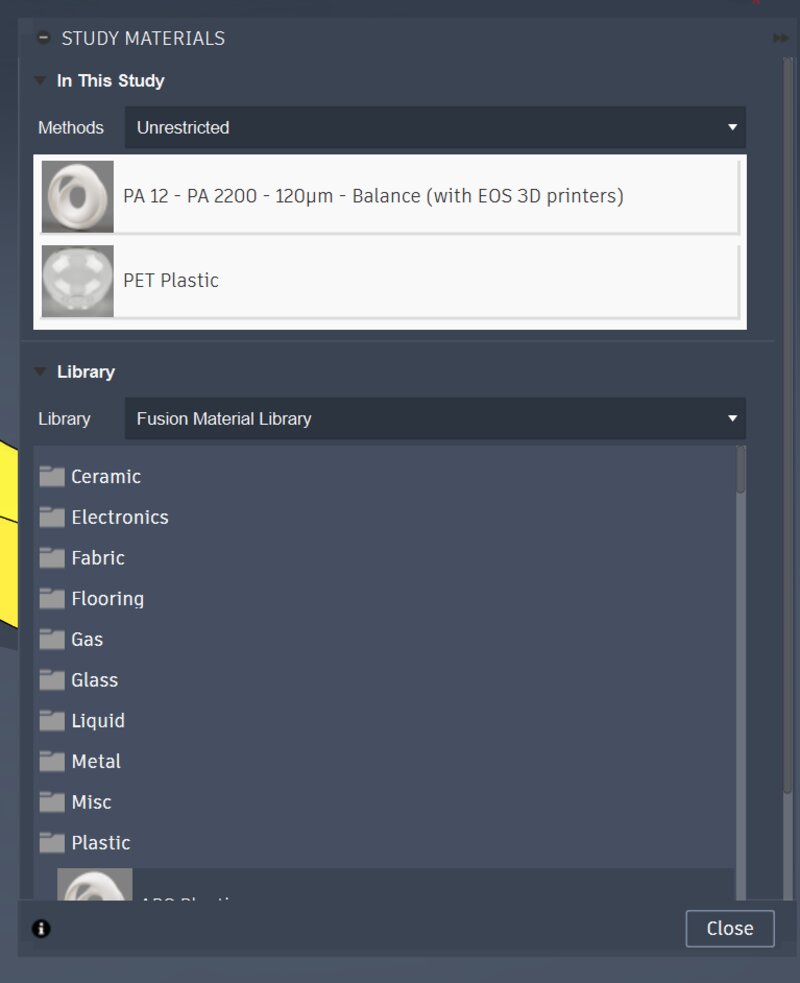
Over in the Manufacturing tab we can select materials.
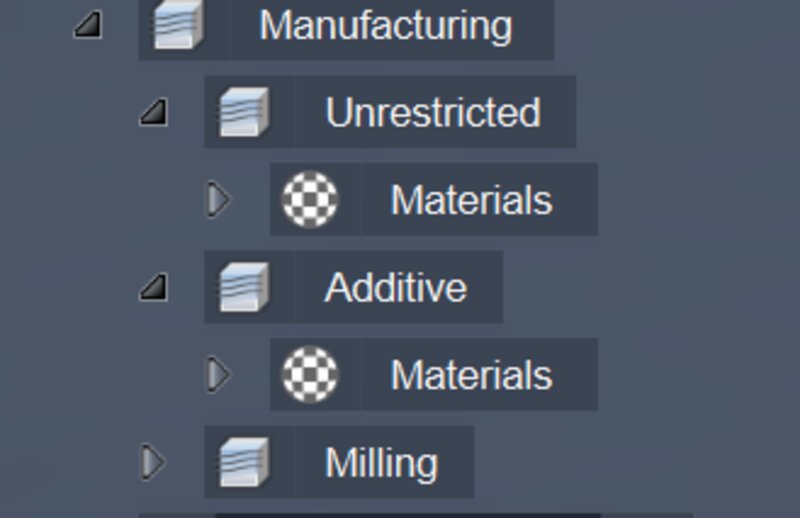 I've added PET since there isn't PLA in the library.
Also make sure you have a constraint.
 This can be added by pressing
 C.
Now we can run the case!
When running a study I first recommend running the pre-check.
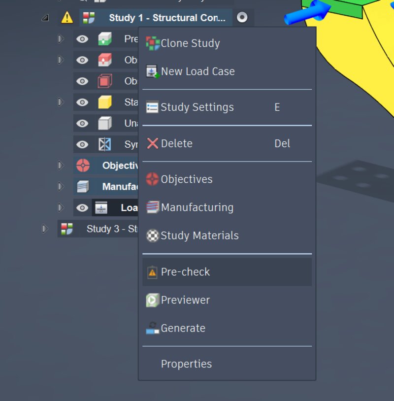 In my case I am not milling it and the part that's hidden is the motor itself so that's fine.
So now I am ready for generation.
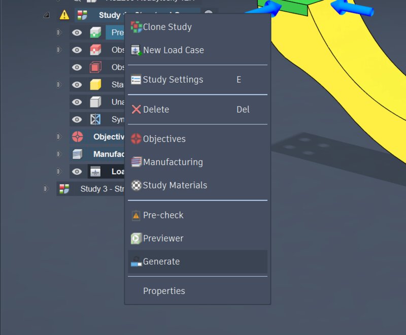 Once I press that button this will pop up and I can press Generate 1 Study.
This does cost money If you don't have unlimited cloud tokens. With my education license I do have unlimited.
Once I press that button this will pop up and I can press Generate 1 Study.
This does cost money If you don't have unlimited cloud tokens. With my education license I do have unlimited.
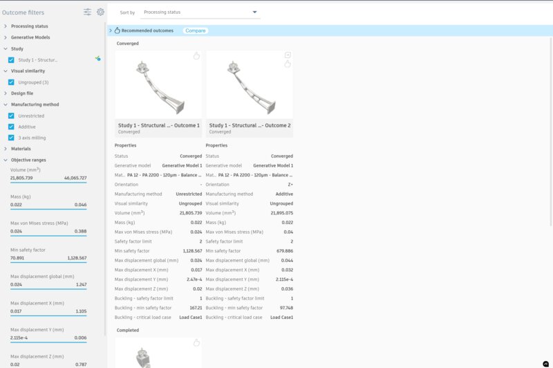 Once it starts generating this will pop up. These are the finished results. The generation process can take about an hour.
Full redesign
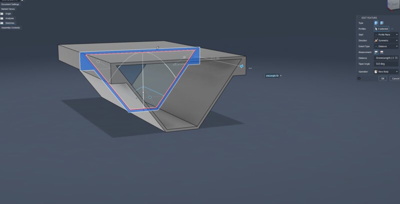
I started a full re-design from the ground up because the old design was too cluttered and it didn't scale properly anymore parametrically. I first started off with the first sketch from the original design.
From there I extruded the body symmetrically so they are always the exact same size on both sides.
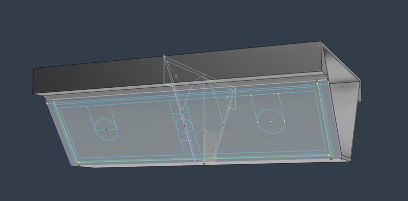
I made a sketch on the side of the drone making place for the LED matrix and all its cables
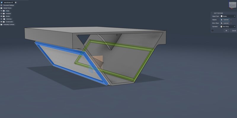
After that I used the mirror tool to mirror the features over to the other side using the axes as the tool since they are dead centre. I did the same for the holes for the wiring
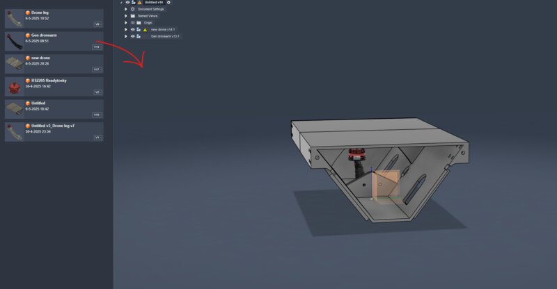
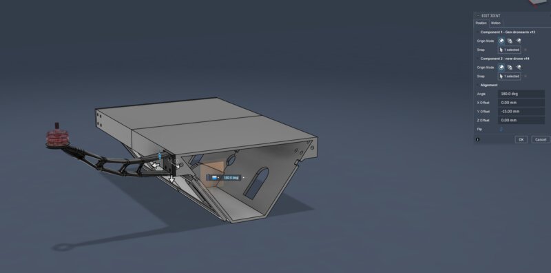
 After that I dragged the motor arm design into the designing window and jointed it to the body of the robot.
Then that I jointed the arm to the robot in the corner.
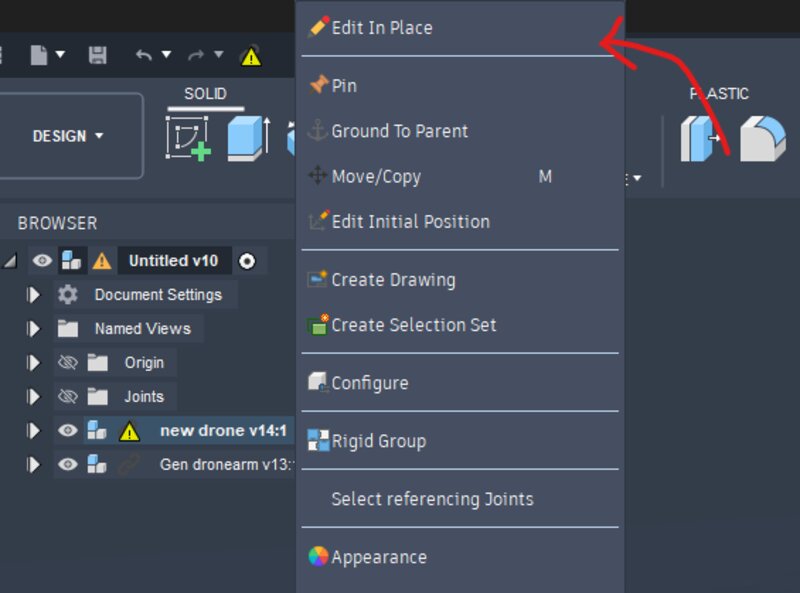
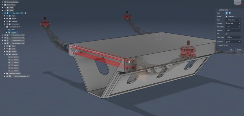
Now I needed to make the same holes through the case itself in the same location. So I choose edit in place from the menu.
From this tab I can edit the body with all the references in place. So I could use the holes in the drone arm as reference for my cuts for in the drone body.
3D printing
I chose to fully 3D print my drone due to it's complex shape and time constraints. I still had a lot of work from university to do. We got encouraged to do compositing but that is super hard with the current design. However it would have been better since it is often lighter and more durable while being a lot more eco friendly. For 3D printing I am planning on using PLA because it has a lower carbon footprint than ABS and it releases less toxic fumes.
Burnout!
Part 1
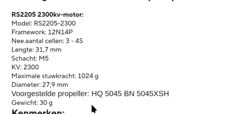
One of my motors during testing burned out completely when it was attached to the printed arm. I think the cause for this is overheating due to a propellor that's too big.
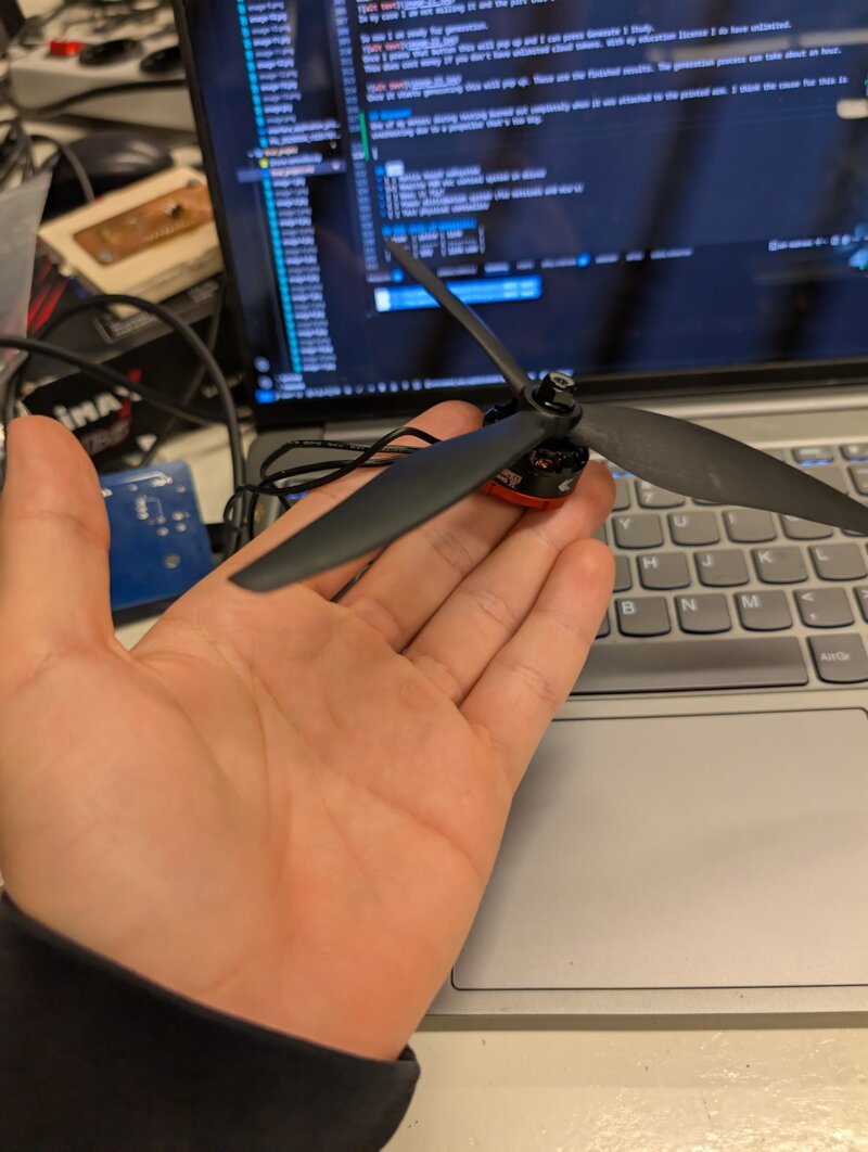
These motors where originally made for 5 inch propellors instead of 8 inch so that's kinda a big difference.
Another thing that also could be the issue is that my ESC was surging above 40 Amps and the motors could only take up to 40 amps.

I think the main reason was heat and the coating on the motors evaporating causing a chain reaction.
Part 2
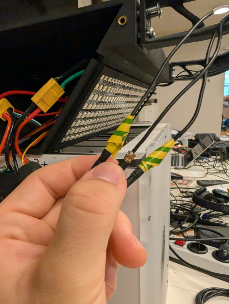
This time it was completely my fault for not paying attention to the wires when connecting them to the right terminals. I had all other motors taped off like this but I forgot to do that for one motor I was testing.
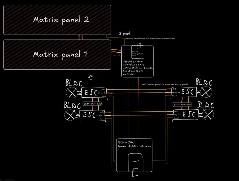
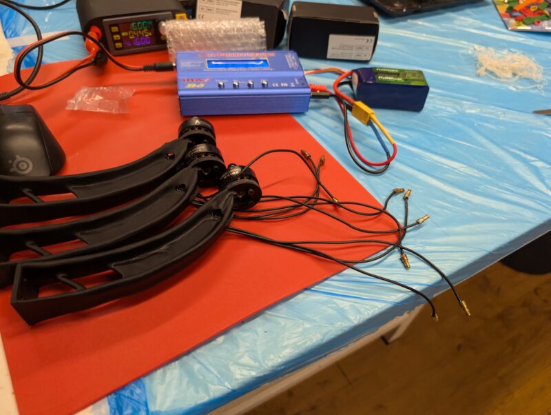
Cables
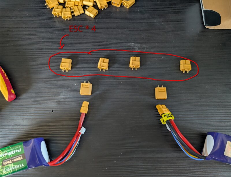
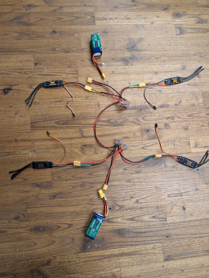
The drone needs lots of cables to get power to the places where they need to be. I first started out by laying out everything that needed to be connected.
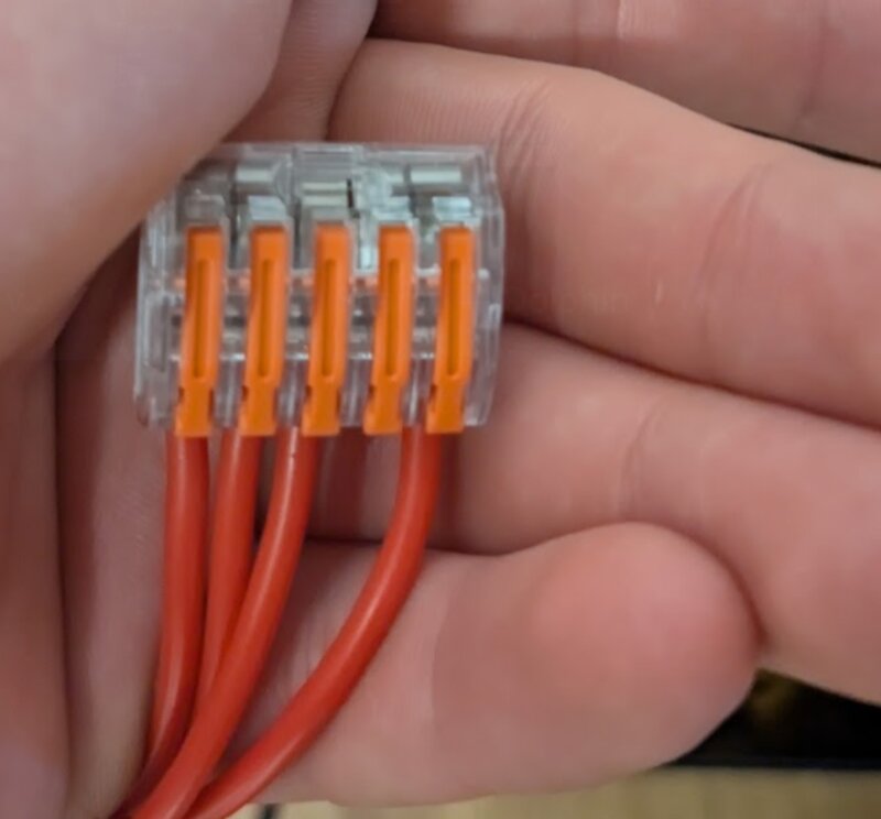
 I first wanted to solder all the joints together but then I remembered how it looked in the past and then decided on using clips.
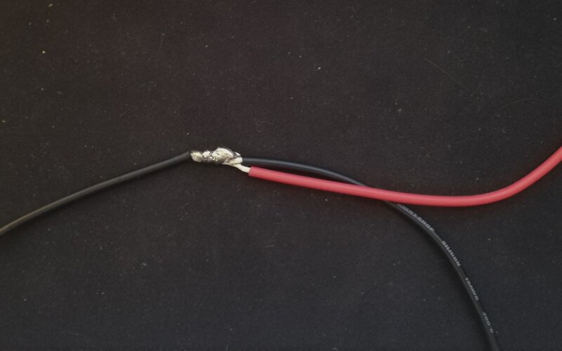
After cutting cables and soldering for a while I made this cable harness.
 I still need to make a new board for both MCU's. The flight controller and the matrix controller.
New board!
Layout
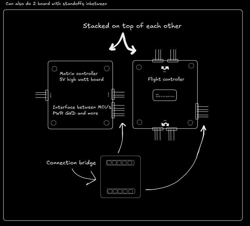
So my new board needs to handle 60 watts of power and a lot of wiring. So I am first going to make a rough sketch of where I want every connector.
I first came up with this. But then I realized how complicated this wiring on a one side board is going to be. So I split it up in 2 boards and then I will stack them on top of each other with standoff screws.
Schematic
I made both boards in the same file.
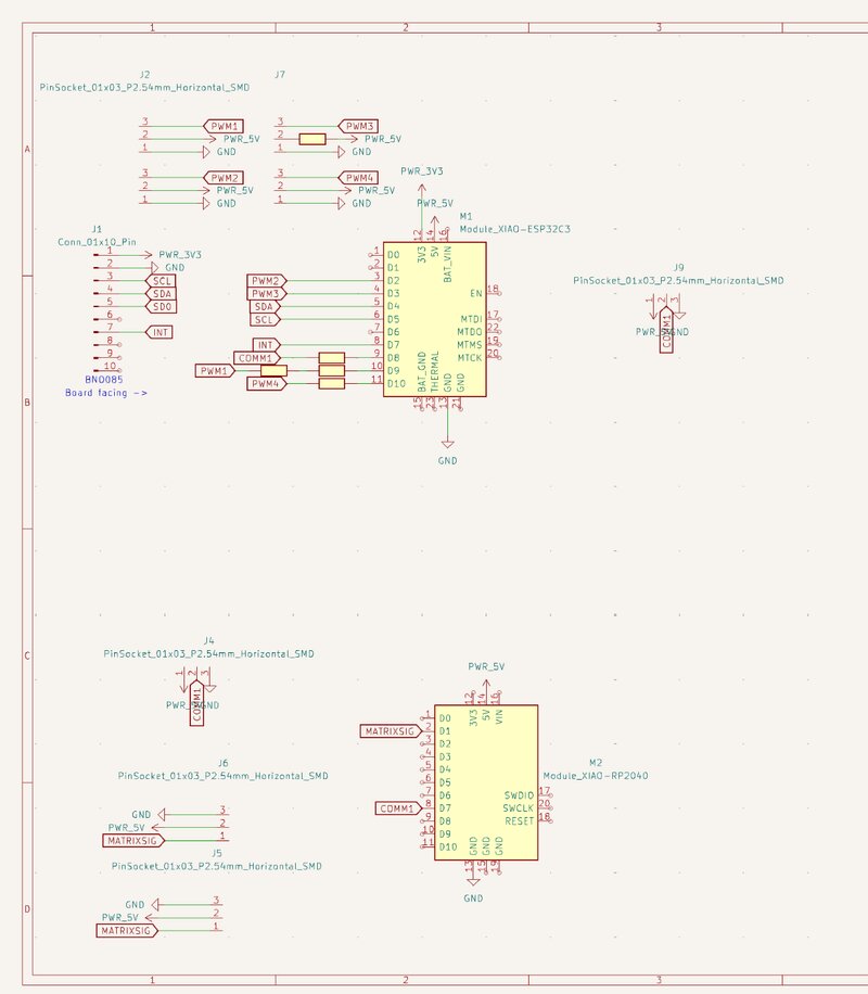 The upper board is the flight controller and the bottom board the matrix controller. I made them in the same file so I could easily copy over the edge cuts so I could stack the boards above each other.
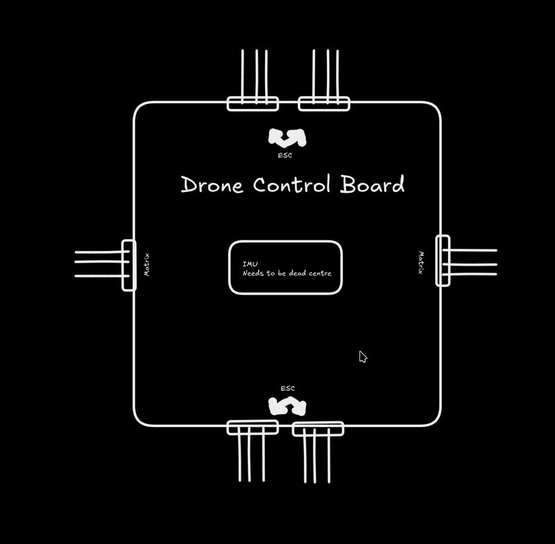
Flight controller
- 4 outputs for ESC's
- One communication pin to other Matrix controller with power and ground
- Input BNO085
Matrix controller
- Communication from flight controller
- 2 output LED Matrixes
PCB
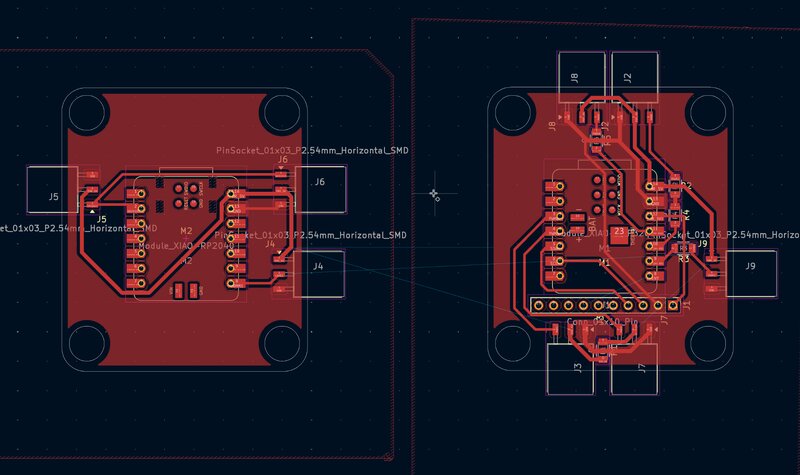
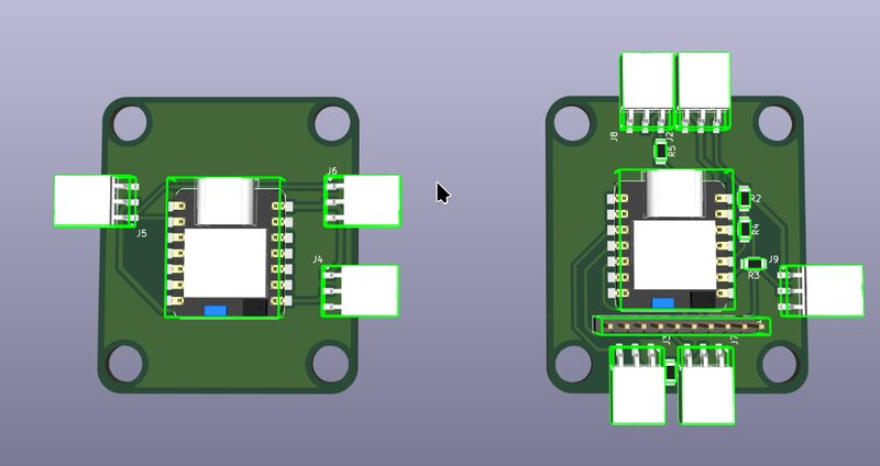 These are the 2 pcb's I designed I first thought it would be handy to make them both in the same file. So I could align the holes so they could be stacked. But later on I realized that was a bad idea because I couldn't export them individually. So my solution was to cut them in gimp for each layer. When cutting you have to make sure to cut every layer in the same place otherwise during milling the layers may not match.
Matrix subsystem
Power
I tested the power consumption on the matrix by setting the brightness to 100 and the colors to white since white consumes the most amount of power.
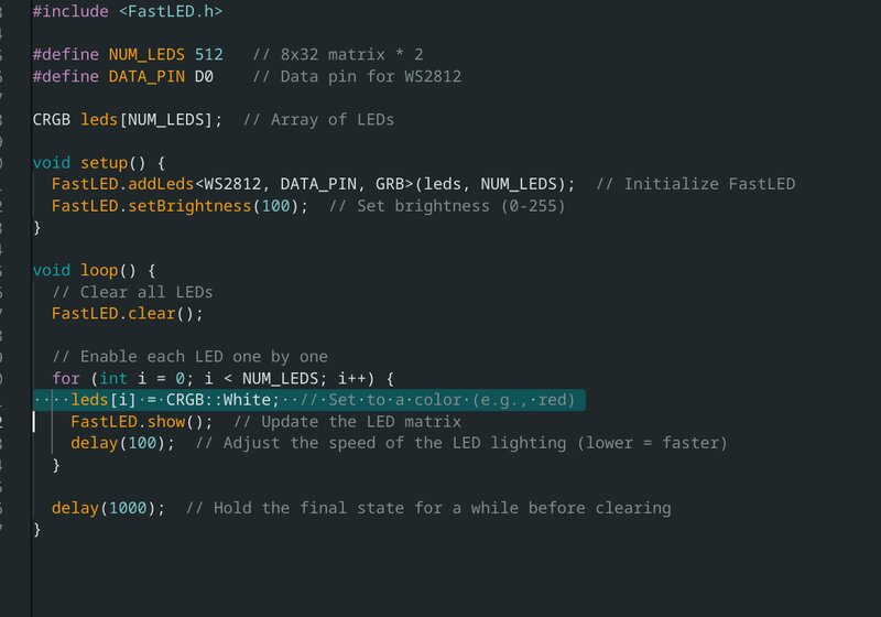
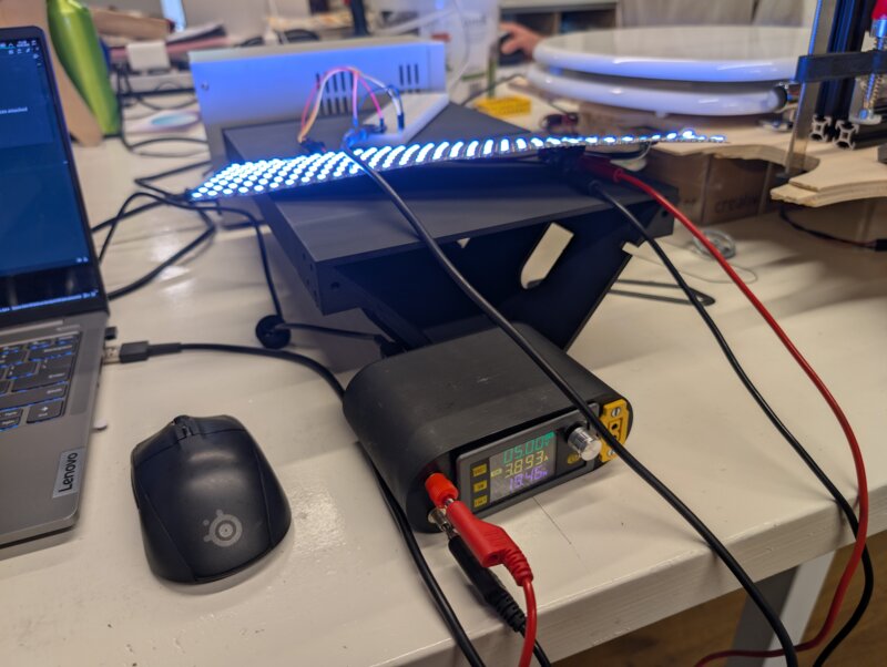 The result of this is that a single matrix consumed 3,8 amps at 5 volt. With 4 ESC's providing a total of 12 amps at 5 volts I should be easily able to power the mcu's and the matrixes.
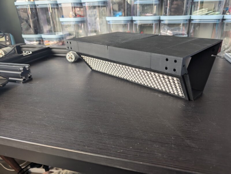
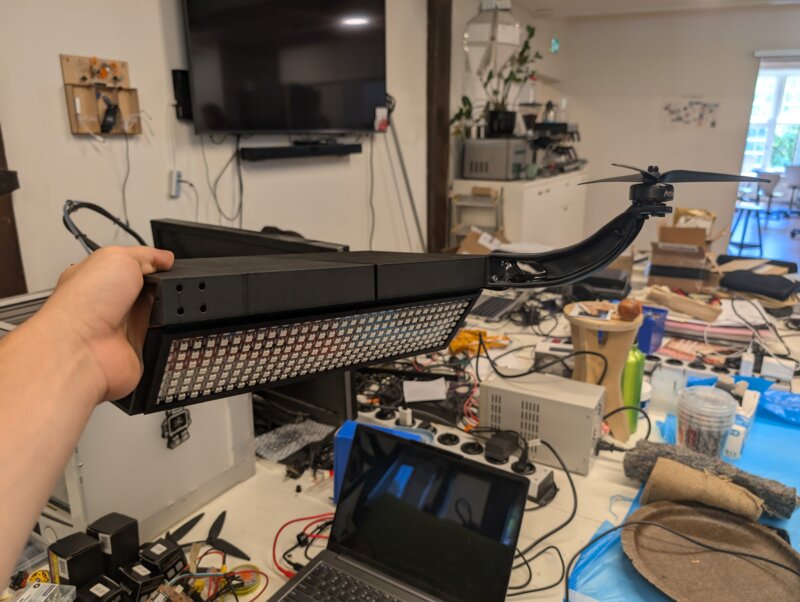
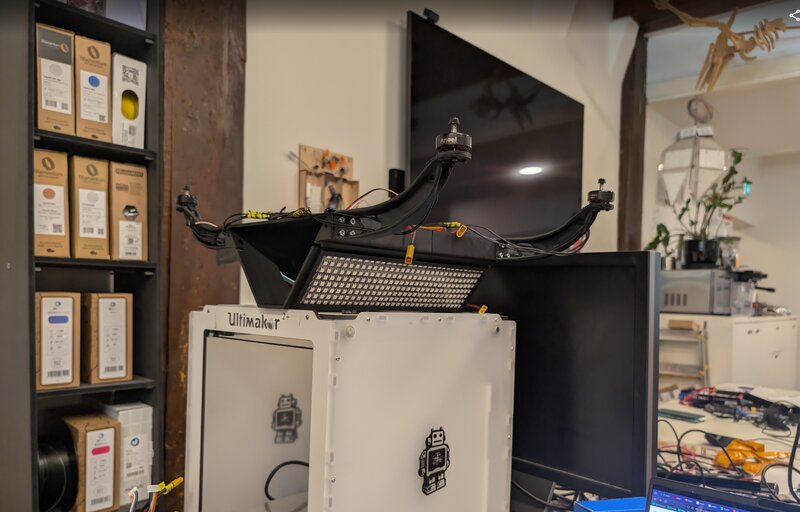
Assembly
Here I started assembly of the drone. I printed the motor arms and screwed all the motors into them and soldered pogo pins to each to connect them to the esc's. Unfortunately I don't know how to connect them yet because the wires aren't labeled. 2 motors need to spin left and the other 2 right for stability.
 I also saw during assembly that the drone body warped a bit but that isn't going to ruin the fun. It will still fly.
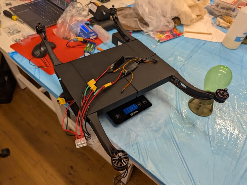 The weight without the propellors and batteries is 1347 grams. The propellors weight a few grams and each battery weighs 183
$$1347 + 183 * 2 = 1713 grams $$
The weight without the propellors and batteries is 1347 grams. The propellors weight a few grams and each battery weighs 183
$$1347 + 183 * 2 = 1713 grams $$
Kaboom
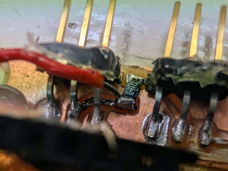
I accidentally killed an esp C6 due to short in between the PWM output pin of the mcu and the 5v inputs of all electronic speed controllers. That's 5V 12Amps running through the mcu. The first few tests I was lucky that I didn't plug anything into the shorted connector but when connecting everything the mcu got killed. I sadly can't repair the board since there is hot glue everywhere to keep the connectors on the board.
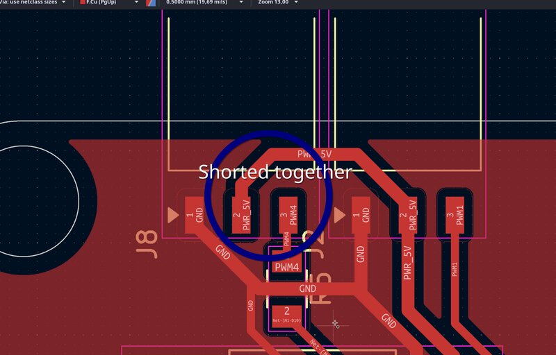
Later on I realized I also killed my IMU. Because there wasn't any resistance between the 3v3 and the GND
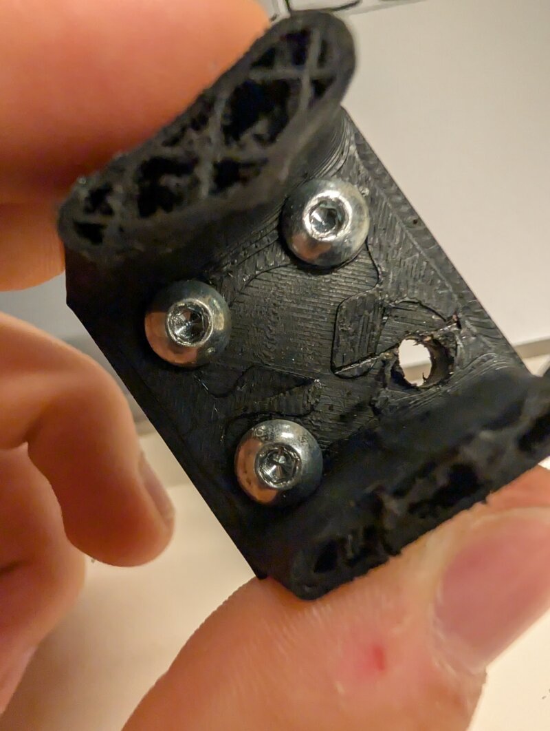
Stripped screws
Quick tip. When tightening screws do not do it at an angle otherwise you may strip the screw or dislodge the heated insert. Learned that the hard way. ;-;
And when doing heated inserts make sure to do a couple of extra wall layers. So the heated insert can latch onto the plastic.
TODO
- Matrix panel subsystem
- Rewrite PWM esc control system in driver
- Does it fly? (No it didn't)
- Power distribution system (for matrixes and mcu's)
- Test physical controller
Testing the drone(V1)
The first test of the drone went horribly wrong. This was a first test with analog control with not stabilization feedback from the IMU to see if it would come off the ground. Sadly it did not go as expected.
What went wrong
- The drone was not balanced
- The drone was a bit too heavy
- The drone didn't have good footing to the ground
- Motors recalibrating themselves at some startups (Last startup that didn't happen)
- The drone arm was too weak to resist the impact of the motors
- The batteries weren't fastened inside the drone
Improvements for next design
- Proper legs so the drone doesn't fall over during takeoff
- Lighter design while being as strong as possible with the least amount of material
- A power switch because everything instantly starts once it gets power and that could be dangerous with extremely fast spinning propellors.
- Fastened batteries
The damage
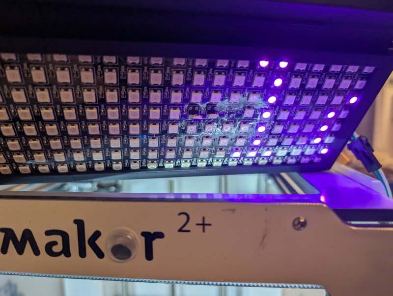 One matrix board got a few ripped of leds and capacitors but I think I am able to repair that.
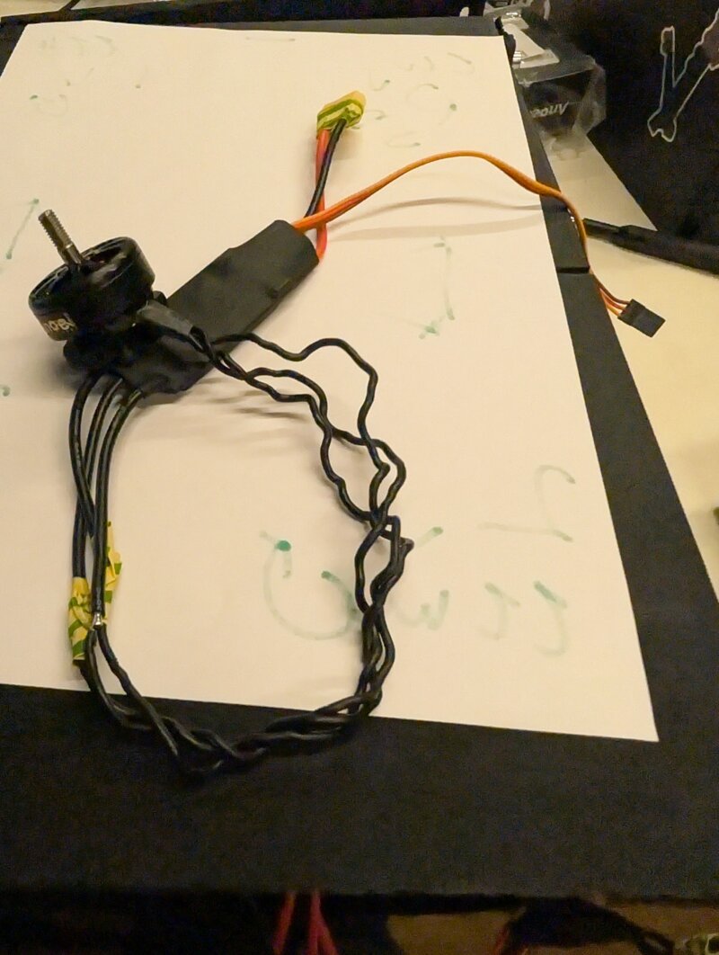 2 ESC's and motors got completely tangled wires. I expect them to still work since they where still spinning after the impact.
3/4 arms got ripped off due to the crash.
2 ESC's and motors got completely tangled wires. I expect them to still work since they where still spinning after the impact.
3/4 arms got ripped off due to the crash.
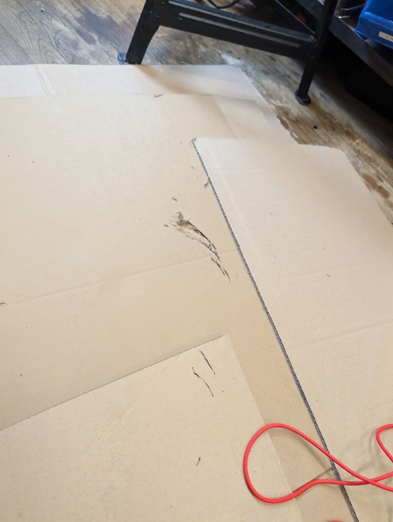
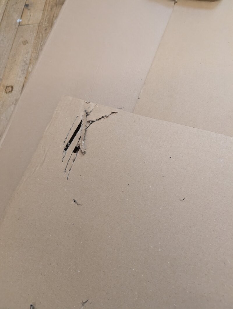 Luckily we placed cardboard under the drone incase something would happen. The propellors completely mauled the cardboard away where it hit.
Now that the drone is ripped into several pieces I will be abandoning this design and start from scratch on a second design. From this point on I can only go up.
BOM (bill of materials)
Drone
Parts
| item | price | link |
|---|---|---|
| 700 grams of filament | € 14 | Any PLA |
| Matrix panel * 2 | € 17,78 | https://aliexpress.com/item/4001296811800.html |
| BLDC ESC * 4 | € 26,76 | https://aliexpress.com/item/1005006947824850.html |
| BLDC Motor 1500KV | € 34,39 | https://aliexpress.com/item/1005006859037930.html |
| 4S Li-Po * 2 | € 15,86 | https://hobbyking.com/en_us/turnigy-nano-tech-plus-1400mah-4s-70c-lipo-pack-w-xt60.html |
| Propellors 7040 | € 6,99 | https://aliexpress.com/item/1005008125599756.html |
| XT-60 connectors | € 1,40 | https://aliexpress.com/item/1005007228544590.html |
| Wiring 26 AWG | € 1,63 | https://aliexpress.com/item/1005007213319794.html |
| seeed XIAO RP2040 | $ 3,99 | https://www.seeedstudio.com/XIAO-RP2040-v1-0-p-5026.html |
| seeed XIAO ESP-C6 | $ 5,20 | https://www.seeedstudio.com/Seeed-Studio-XIAO-ESP32C6-p-5884.html |
| smd male header pins | € 2,99 | https://aliexpress.com/item/32796117265.html |
| M4 screws and nuts | https://aliexpress.com/item/4001072025844.html | |
| M4 Threaded inserts | https://aliexpress.com/item/1005003582355741.html | |
Files
- Drone main body F3Z
- Drone arm F3D
- Drone main body STL
- Drone main arm STL
- Drone side panel STL
- Drone PCB's KiCad
- Drone Software
- Matrix Software
Drone controller
Parts
| item | price | link |
|---|---|---|
| XIAO ESP-C3 | $ 4,99 | https://www.seeedstudio.com/seeed-xiao-esp32c3-p-5431.html |
| Hall effect joysticks | € 11,99 | https://aliexpress.com/item/1005007462081151.html |
| Analog Multiplexer IC | $ 0,57 | https://www.digikey.com/en/products/detail/texas-instruments/CD74HC4067M96/1507236 |