FR-1 Trace lengths
The experiment
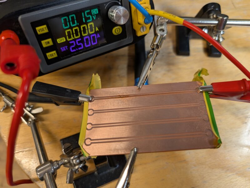
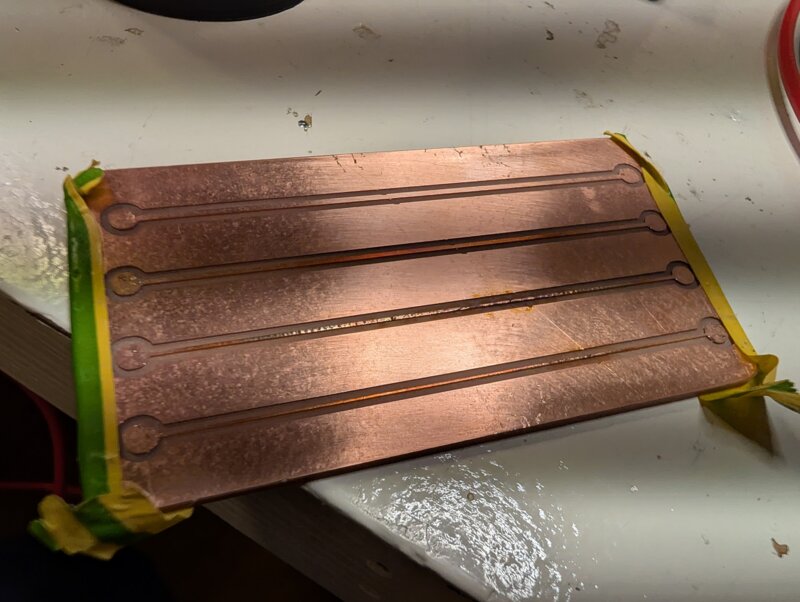
For the experiment, I used FR-1 that has a thickness of 35µm. On there I will mill 4 trace sizes (0.4 mm, 0,6 mm, 0,8 mm and 1 mm) and they all have the same length of 7.5 cm’s. The traces are separated by 1 Cm.
In this experiment I will measure the temperature of the traces with a multimeter and a thermal laser. I will also watch the board closely for any damage. Since it is FR-1 I expect it to shows signs of damage under heat
Some background information
Resistance
When you decrease a PCB trace width, the resistance of the trace increases. Imagine a trace like a water pipe. Whenever you make it smaller the water needs more pressure to flow with the same amount of water. The same analogy goes for electricity. So for longer traces this is also the case that the amount of resistance increases with length. Whenever the resistance increases different things happen when voltage travels trough them. A higher resistance causes a voltage drop. This can be explained using Ohm's law
\(\(V = I \cdot R\)\)
The Voltage drop is Amperage \(\(I\)\) times the Resistance \(\(R\)\). So if you have a higher resistance or a lower Amperage you will get a voltage drop. Another side effect of having a higher resistance is that the resistor or trace will heat up more easily.
Capacitance
The capacitance of a PCB trace is the amount of energy it can hold. It works like a capacitor it stores a small amount of energy. The capacitance is determined by the amount of copper is in the trace. So length, width and the thickness. When working with low frequency signals the capacitance is not super important. But when working with higher speed frequencies the capacitance can actually mess up the signal integrity.
Heat generation
Heat within traces is generated by the current flowing through it. Not the wattage. A good example of the is train lines. These run on 230.000 volts on thin wires while being able to supply multiple trains. The higher the voltage the easier it is the transport a higher amount of wattage.
Results
the power. So I grabbed an old robot with 4 stepper motors attached but I could not get them to draw more than 1.6 Amperage. So that is why the maximum in this test is 1.6 Amperage. I also had a hard time finding a way to measure the temperature of the traces because we only had a heat gun here and the laser was not the place it was actually measuring. So 0,4 mm is not measured properly.
| Trace Width Trace | Resistance | Maximum safe Current in Ampere | Burn out Ampere |
|---|---|---|---|
| 0,4mm | 3.1Ω | 0.7 | 0.85 |
| 0,6mm | 2.7Ω | 0.9 | 1.05 |
| 0,8mm | 2Ω | 1.6 | ?? |
| 1mm | 1.85Ω | ?? | ?? |
-
The 0,4 mm trace was the first one I tested. I started with 0.7 amps for a few seconds. After that I increased the wattage to 0.85 amps and the trace instantly exploded and burned so I could not get temperature readings there.
-
The 0,6 mm trace it held up well up to 0.9 amps where it started getting burn marks within a 5-10 seconds. The temperature rose to 50 degrees celsius. At 1.05 amps the pcb burned out at 68 degrees celsius.
-
When testing the 0,8 mm trace I hit a roof with how much power I could consume with the robot. I could only get up to 1.6 amps and I did not manage to break the trace after powering it for a few minutes. The maximum I found before it started discoloring was 24 watts at 54 degrees celsius. This was measured after it was left on for 2 minutes.
-
I could not get to the 1mm trace because the robot could not draw more than 1.6 Amperage. So thats why these are not filled in the table.
Extra notes on temperature
When something keeps fluctuating in heat it will increase in size and shrink again. This can make it so your board deteriorate faster and make traces break faster. So it isn't recommended to use high wattages in pcb traces.
Recommendations for next time
Make bigger pads to hookup the power easier to the pcb and maybe remove all the excess copper but that takes a super long time.