Designing the drone
Drawing the drone
I have a few concept images above and this is the result my drawings.
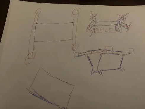
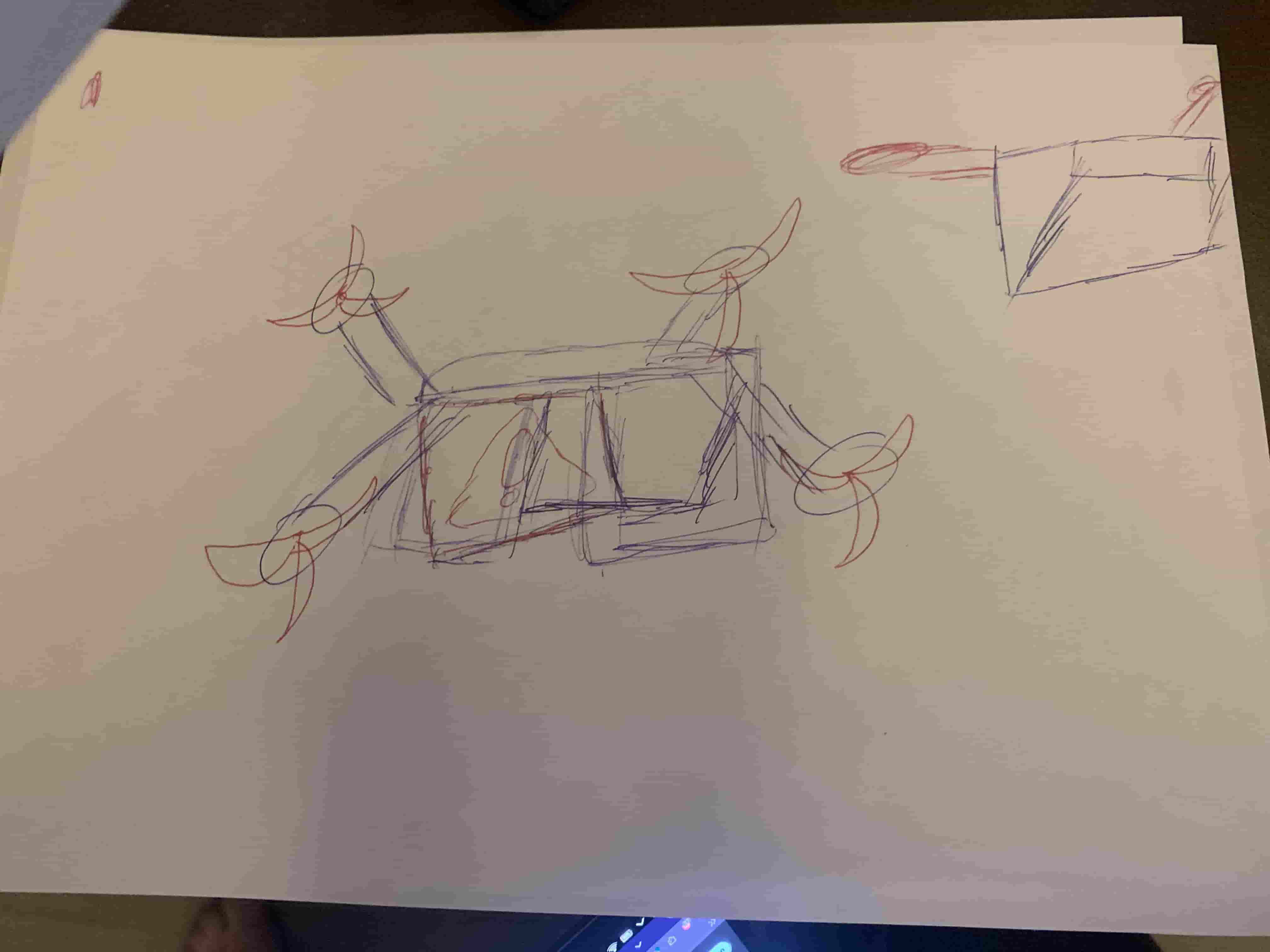
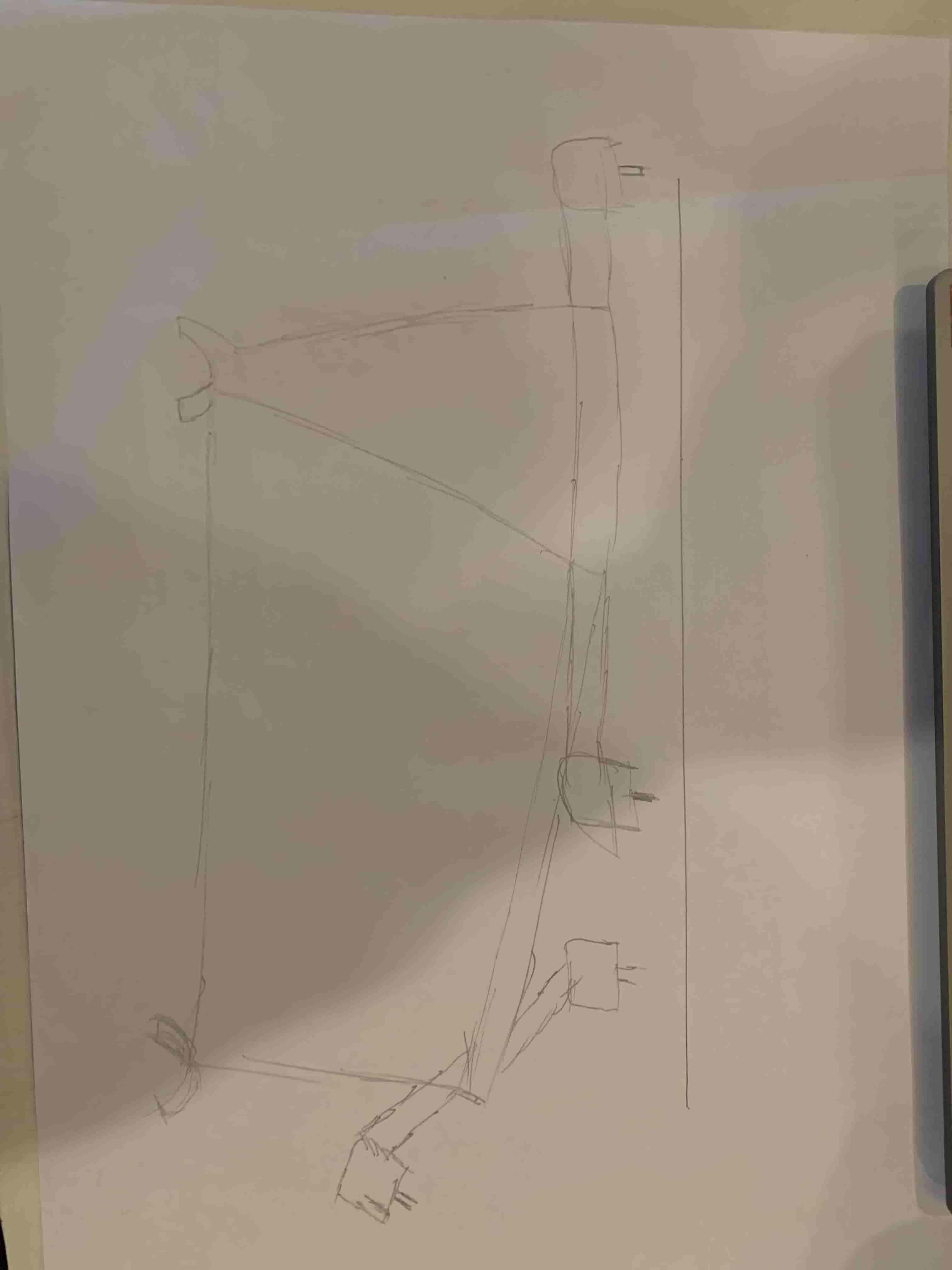
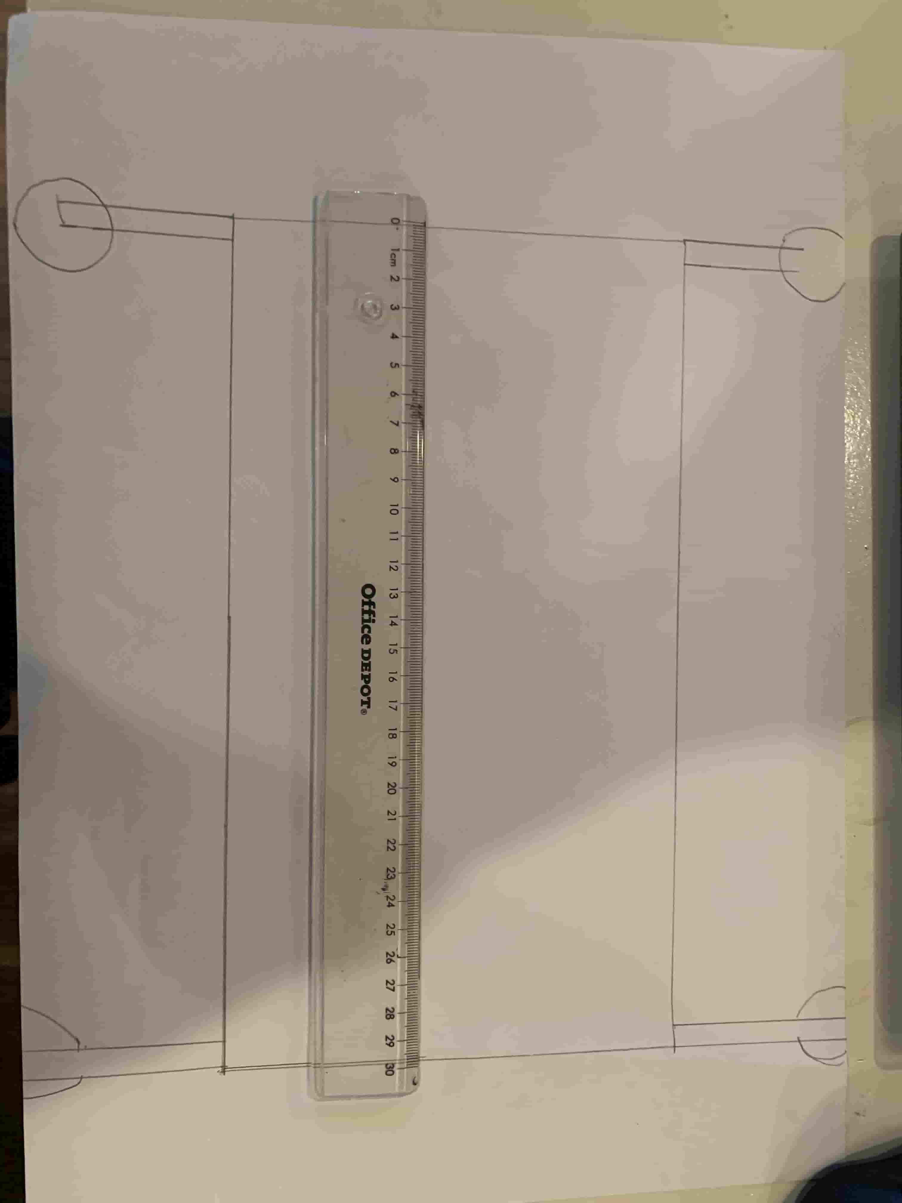
In the second picture you can see that I wanted to make the drone 30 cm in length. But then I looked at the prices for bigger batteries and it started to get super expansive real fast. So I decided to make it smaller. So now im planning on making a drone 10 cm in length. Im still going for the design in the third image.
Designing the drone
When designing the drone I wanted to do everything parametric. So im going to try to use as much variables as possible and make everything depend on each other so everything automatically scales when I change one parameter.
Fusion
I've had a little bit of experience in fusion. Mostly with making basic cases. But now I wanna learn how to design everything perfectly parametric so if I need to change a length everything will scale with it without me needing to fix some things
Previous experience with Fusion360
I've had some experience using fusion with my university for making cases in projects. but it was never explicitly thought to me.
Designing parametrically
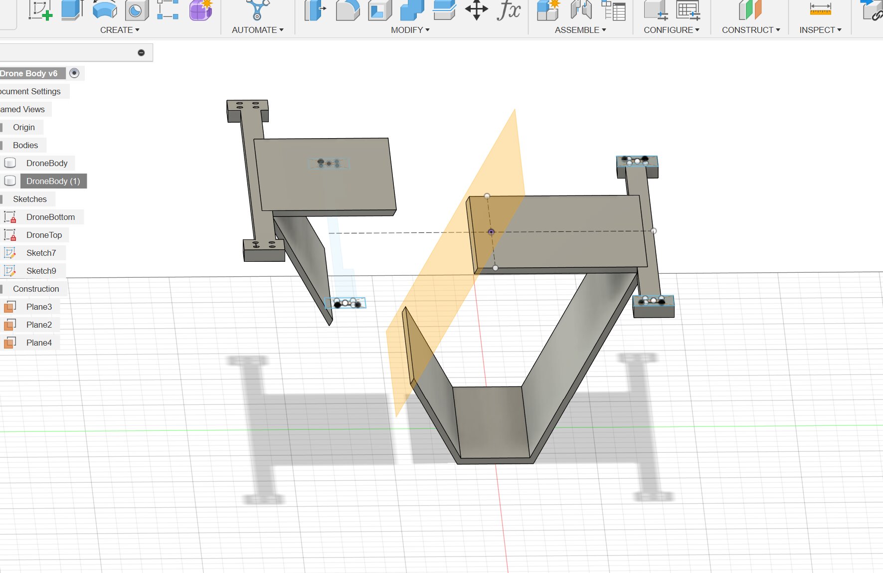
Designing parametrically is very hard because every constraint needs to be perfect. Otherwise when changing lengths the design will fold into itself like this.
What is parametric design?
Parametric design is the practice of using variables in your cad software, so if you wanna change something. Other parts of the design scale with it. It is very handy if you wanna make last minute changes to your design so you don't have to redo the entire design.
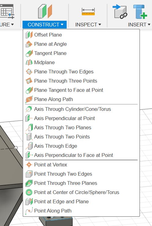
Offset planes
Offset planes are something completely new for me. After the lecture I finally knew what they where and how to use them.
What are offset planes?
Offset planes are a way to tell fusion where you want something to happen. For example the splice tool needs a plane to cut through. For that is a offset plane required. For example I wanna cut this design in half.
Using the the offset planes
For simplicity im gonna start using the normal Offset Plane.
Once that's selected you can select a face to create the offset from.
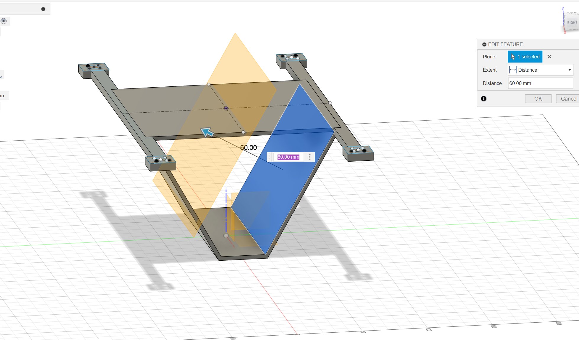
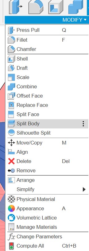
Now we can press split body and select the body and use the offset as a tool to split along to.
The offset planes can be used for almost everything in fusion. You can reference sketches from them and many other stuff.
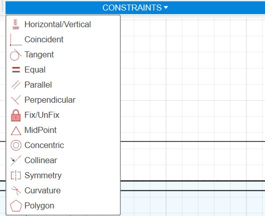
Constraints
There are a few different constraints. When placing things Fusion360 often makes constraints by itself. But additional constraints are needed when making designs parametric.
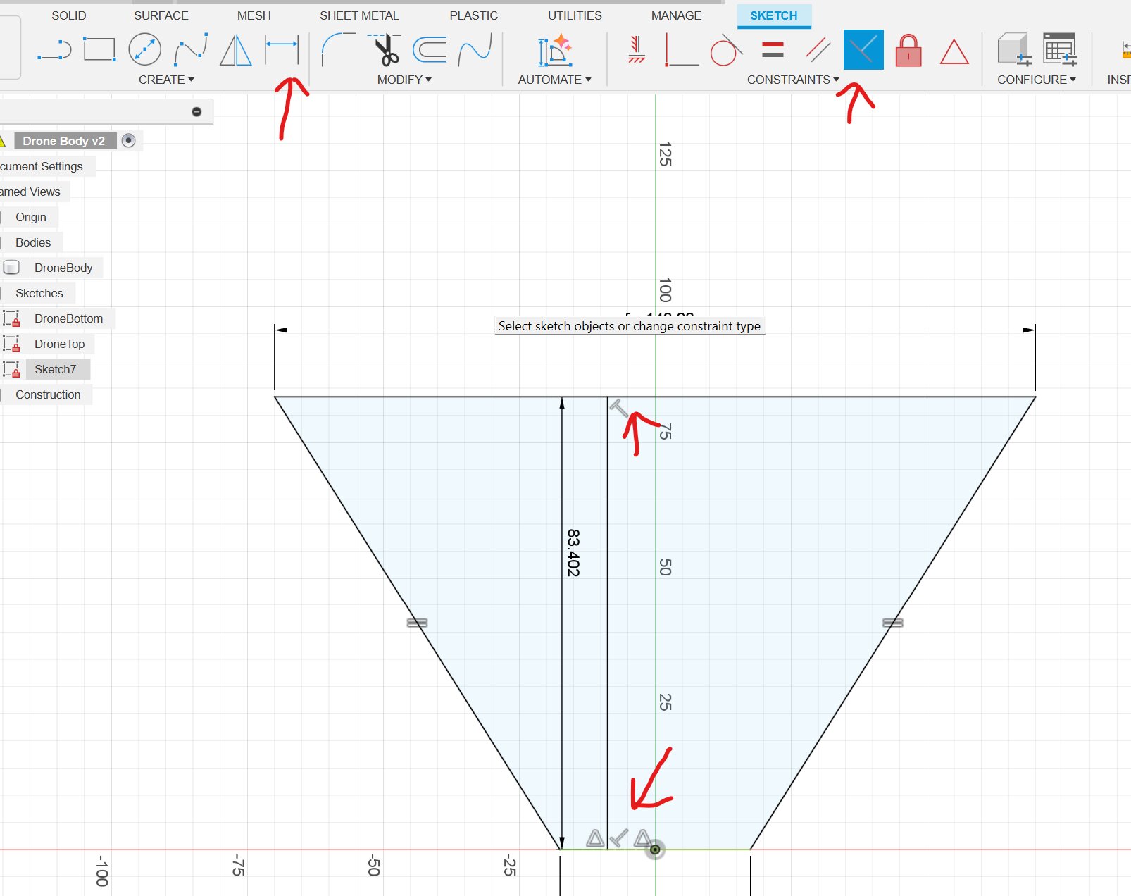
You know when something is fully constrained is when all the blue lines turn black. Sometimes you don't wanna constrain some parts of the sketch because they need to move freely when changing a parameter. For example:
In the first image in fusion 360 you can see what happens when I over constrained it. It didn't scale well with the rest of the design. I solved this issue by removing all existing constraints and from the ground up using the basic shape.
Center constraint
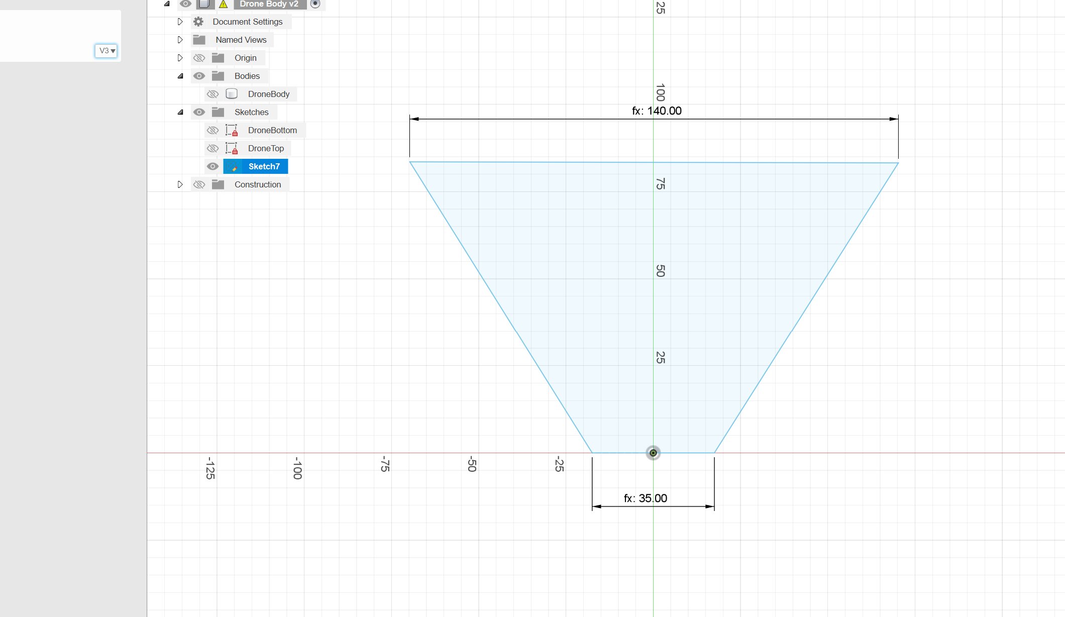
I started off centering the bottom of the design to the center point. I did that by using the Midpoint constraint. Then clicking the origin point and the bottom line.
Lock constraint
Then I locked the bottom line so it can't change rotation or go down when scaling the sketch. When using the lock/unlock constraint the line will turn green and then you know that line is locked in place.
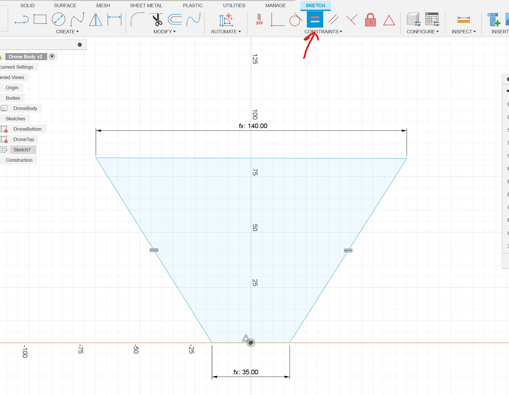
Equal constraint
After that I made both sides of the line equal because the drone always needs to be symmetrical and otherwise you get off angles and that doesn't look nice.
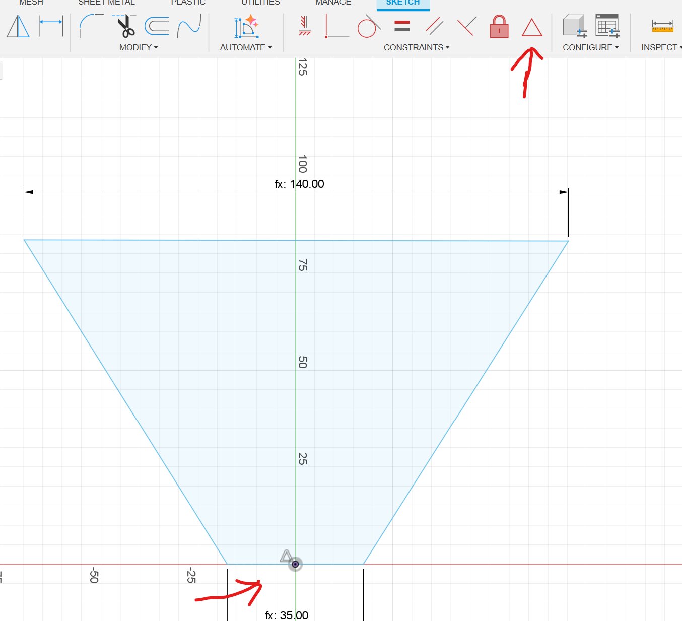
Perpendicular constraint
After that I added a line from Top to bottom and added a perpendicular constraint to both sides so the sketch would always push up and down straight. Once I've made sure both the top and bottom parts of the line.
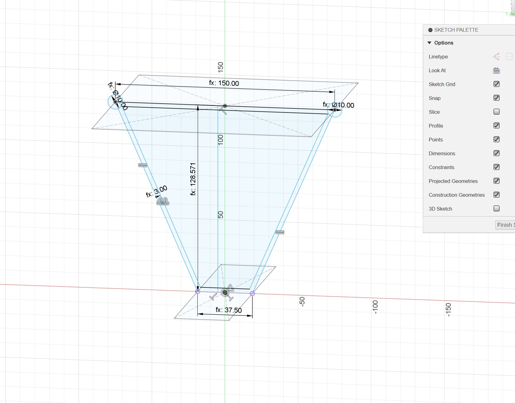
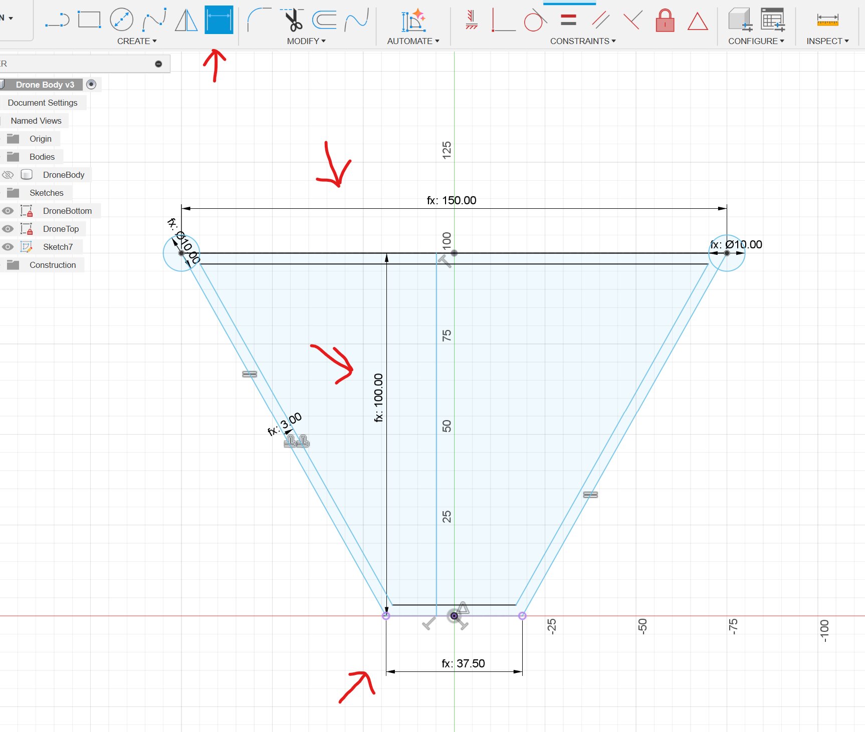
Sketch Dimensions
Sketch dimensions are one of the most important things to use. They tell a line how long it needs to be and it makes sure it can't be any other length. I want the bottom and top of my sketch to always be a certain value. For the sides it doesn't matter because if the top and bottom are defined the rest can be calculated if everything is constrained right. I also want the height to work parametrically so that's why I added a center line with a dimensions.
Extruding
After making all the sketches it's finally time to extrude. To extrude you first need to click a face. What is a face? A face is the light blue part of a sketch or it can be a part of a body.
When you've selected a face you can press E and then you can extrude. A new menu will pop up with all the details of the operation.
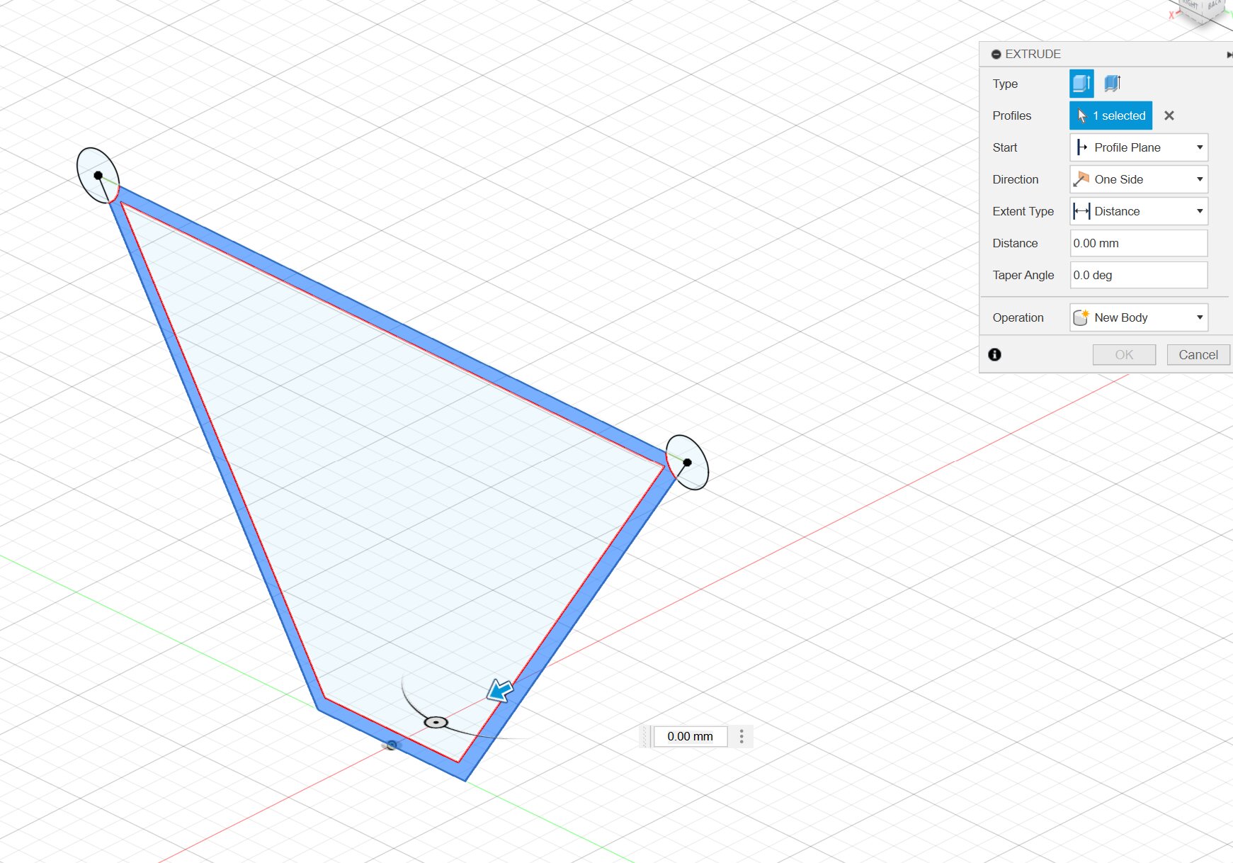
In the menu you will find what type of operation you wanna do, You can join the extrude, create a new body from it, intersect or remove part of a body using extrude. You can also specify the length and how you wanna extrude.
Adding in components
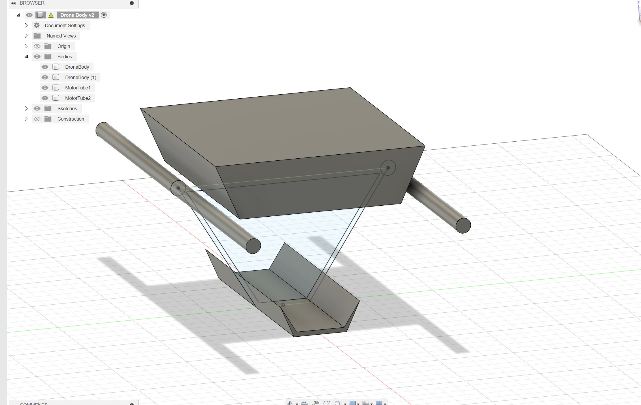
I wanted a digital reference on how the drone would look so I have looked for online components so I wouldn't have to make them myself.
I first searched for Brushless motor 3d design and instantly found a model on grabcad and downloaded it. After downloading it I imported it into fusion360 using the import button in the top left of the project menu.
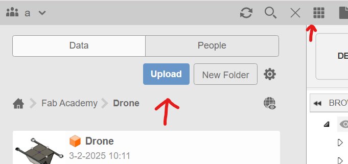
After importing it I dragged it into my design and positioned it in the right location.
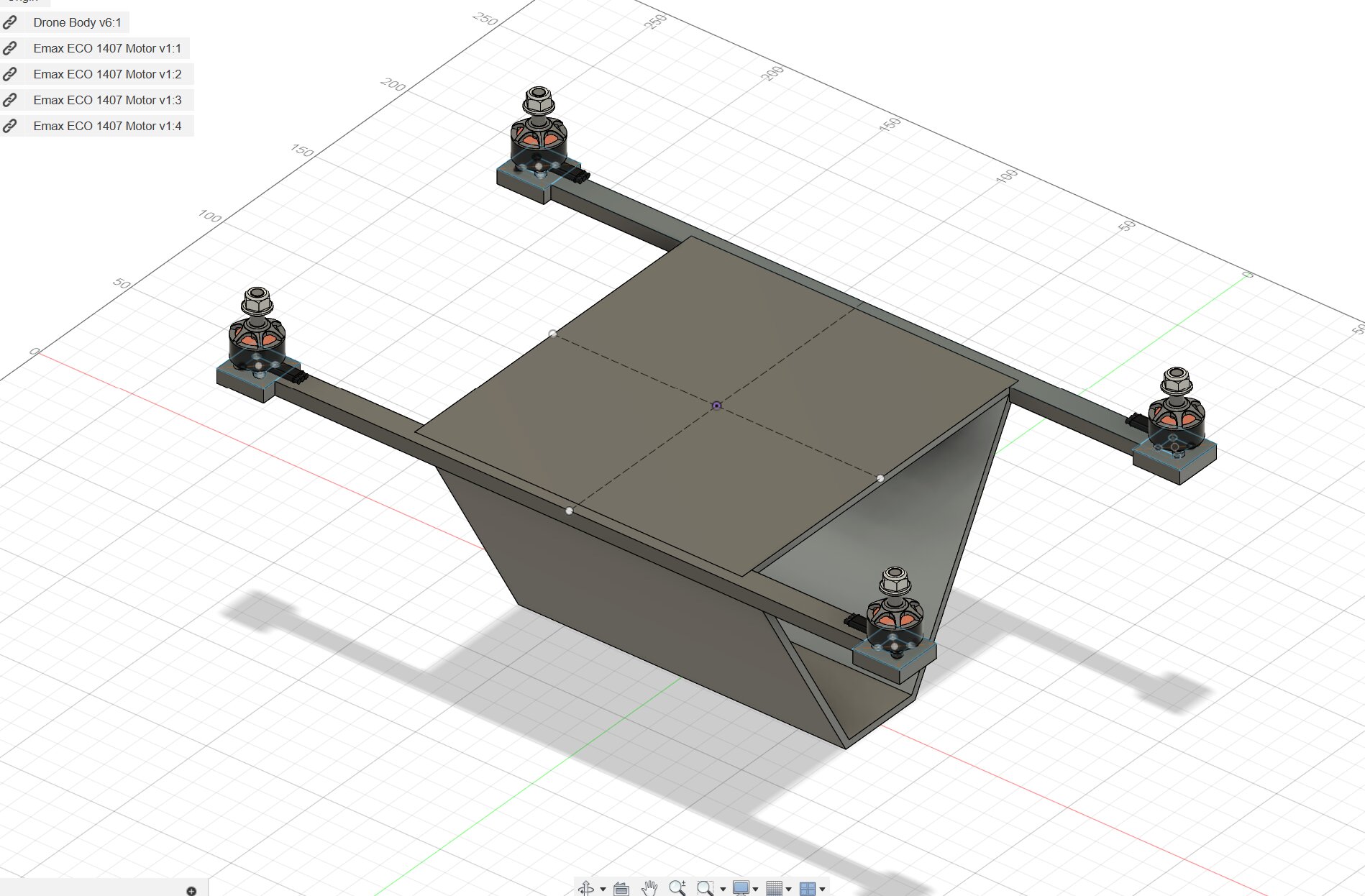
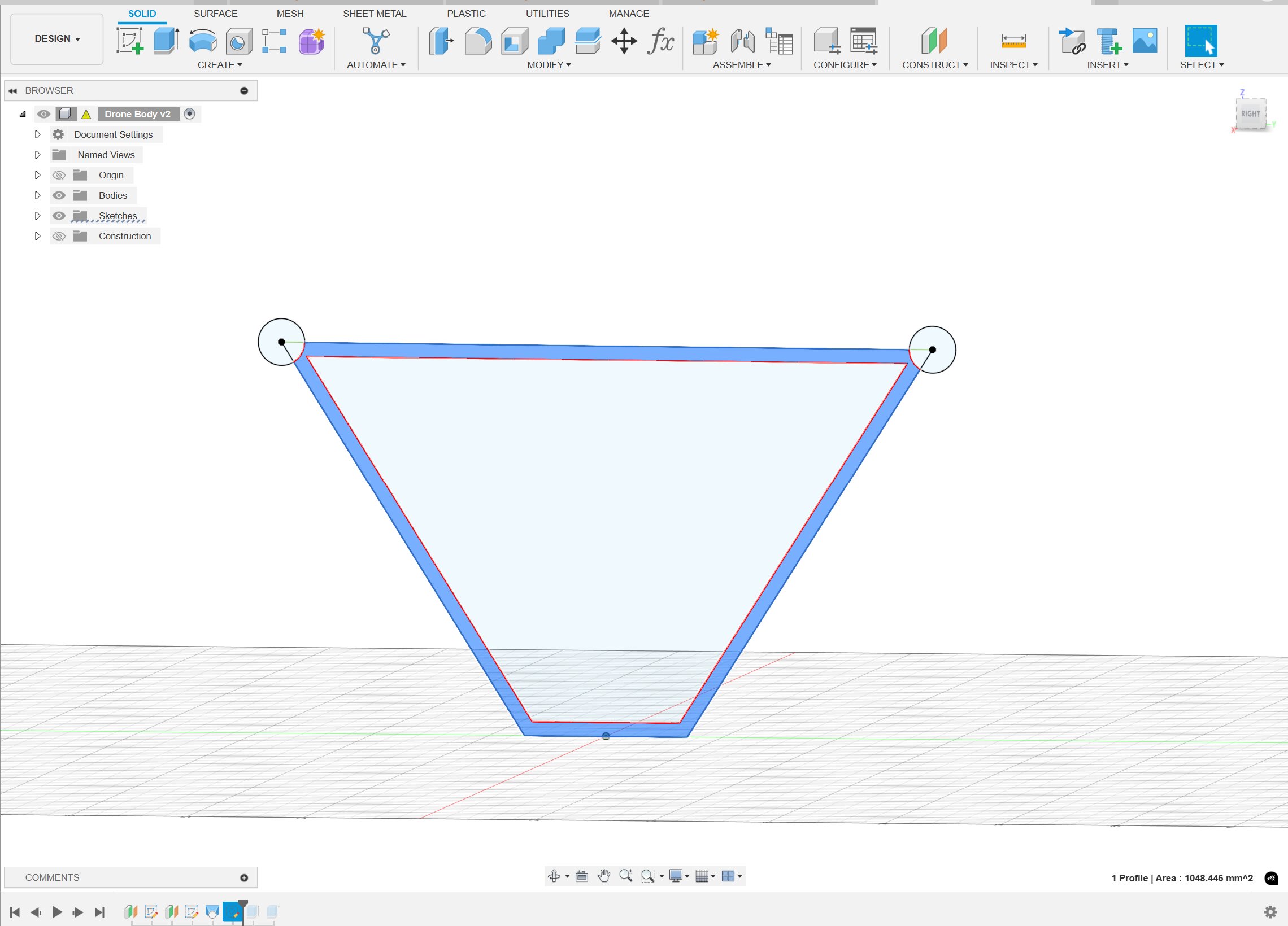
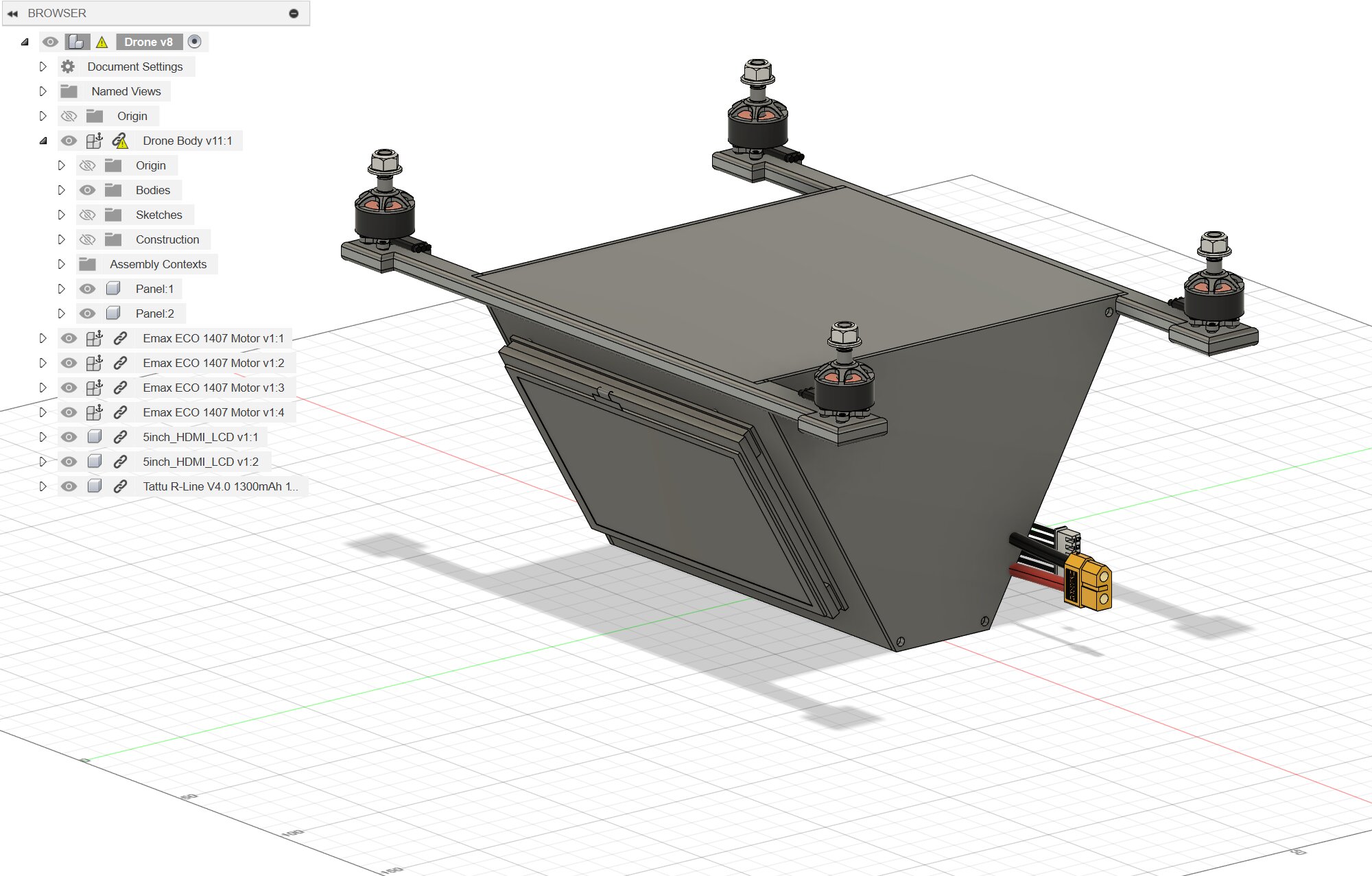
Result
After some time modeling this is my result.
Onshape
Onshape is completely new for me. I've heard engineering youtubers talk about it and promote it but I've never used it myself. That's also why I took some interest in it. So im going to start off with a tutorial.
The first thing im gonna say off the bat is that I like the parameter menu of Onshape way more than fusion. In Onshape it's on the side instead of a new window that you can't use while sketching or modeling like in fusion. The thing that I don't like is that the camera rotates around the center point of the project and that you can't move it freely like in fusion.
Sketching
Another thing thats different from fusion is that you can't instantly give lines variables. You first need to define a length before being able to put in a variable.
I first created the same sketch as in fusion so I could loft the sketches together. 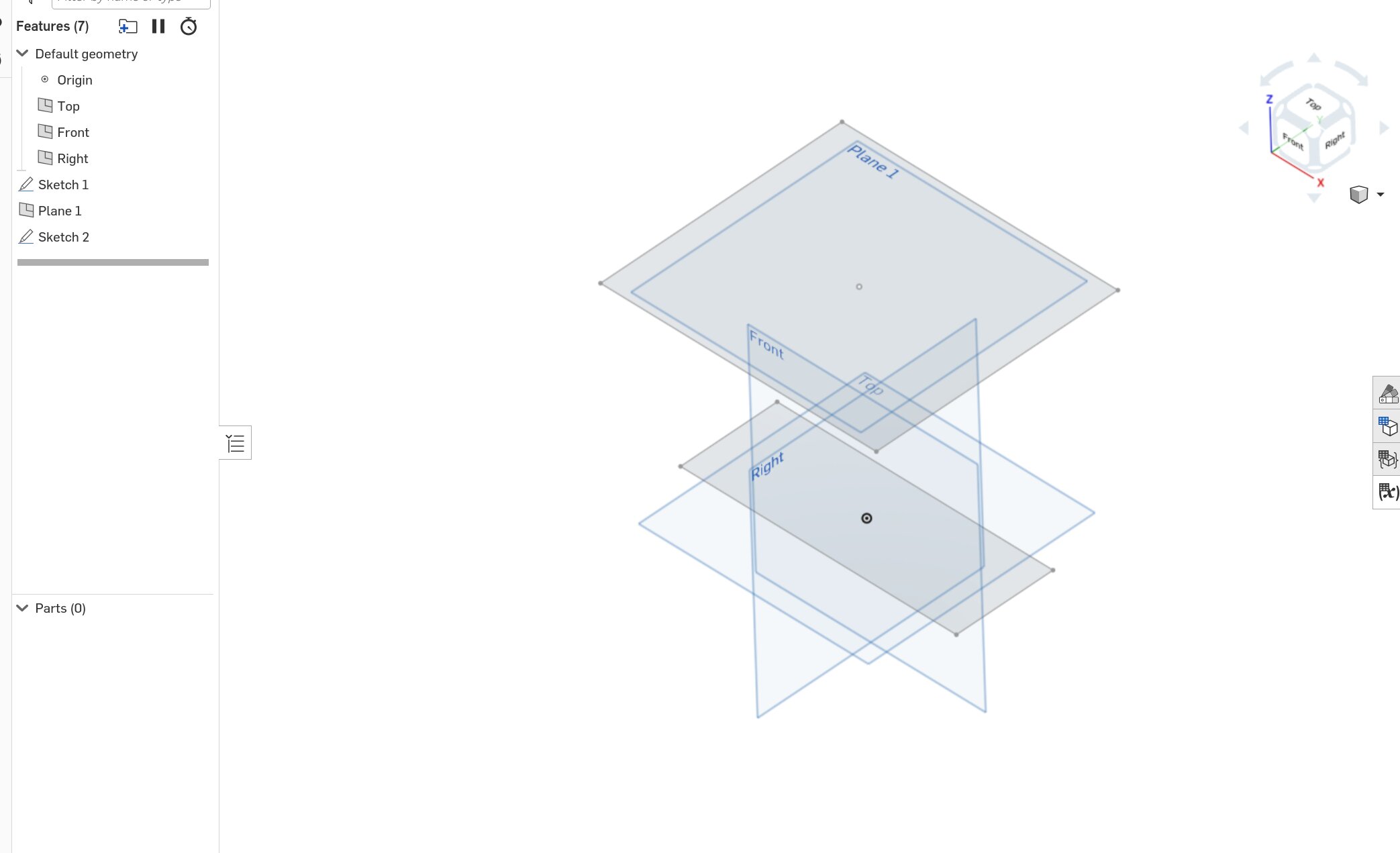
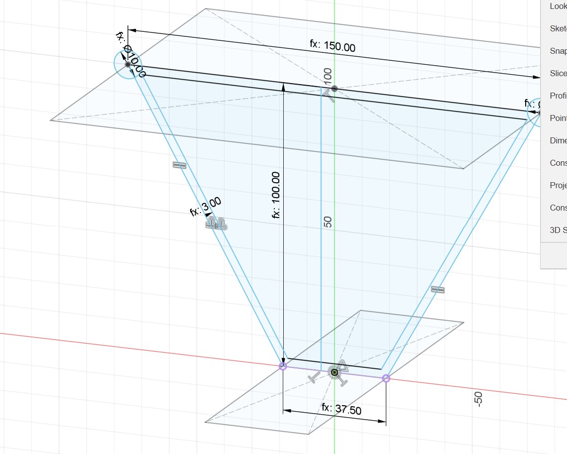
The top sketch was made using a offset plane first and then defining the sketch on top of that.
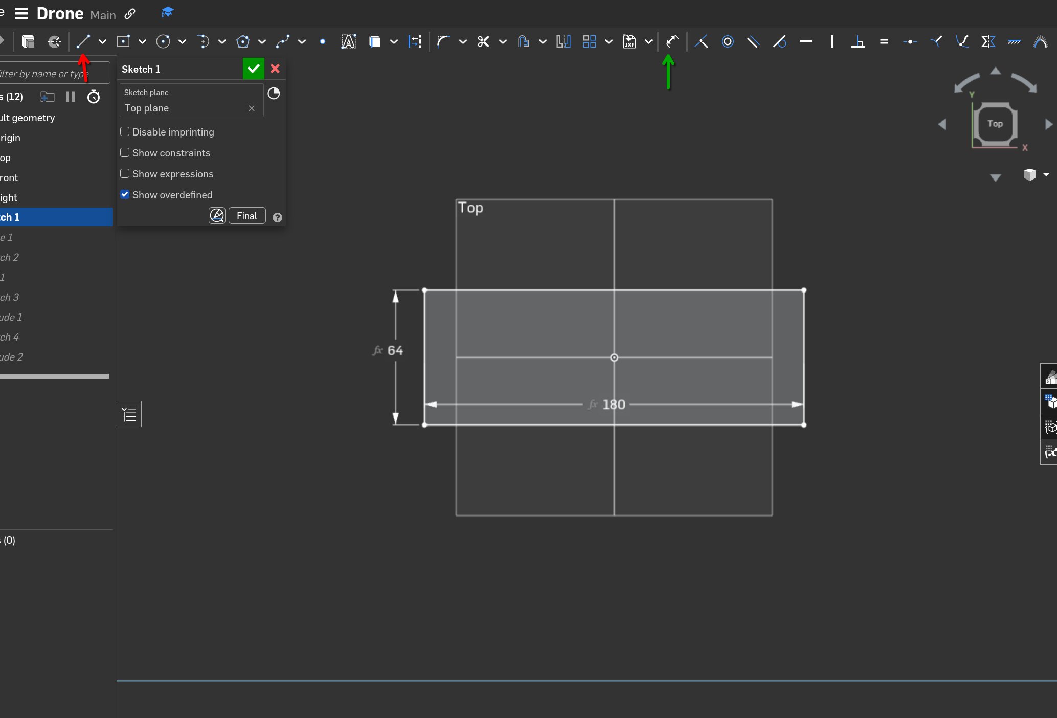
You can draw lines by pressing the button with the red arrow and set the dimensions using the button with the green arrow. It feels very similar to fusion360
Extruding
With Onshape I noticed there are more extrude options available. You can choose through how much walls it should go or you can define the dimensions yourself.
To connect the 2 sketches I used loft.
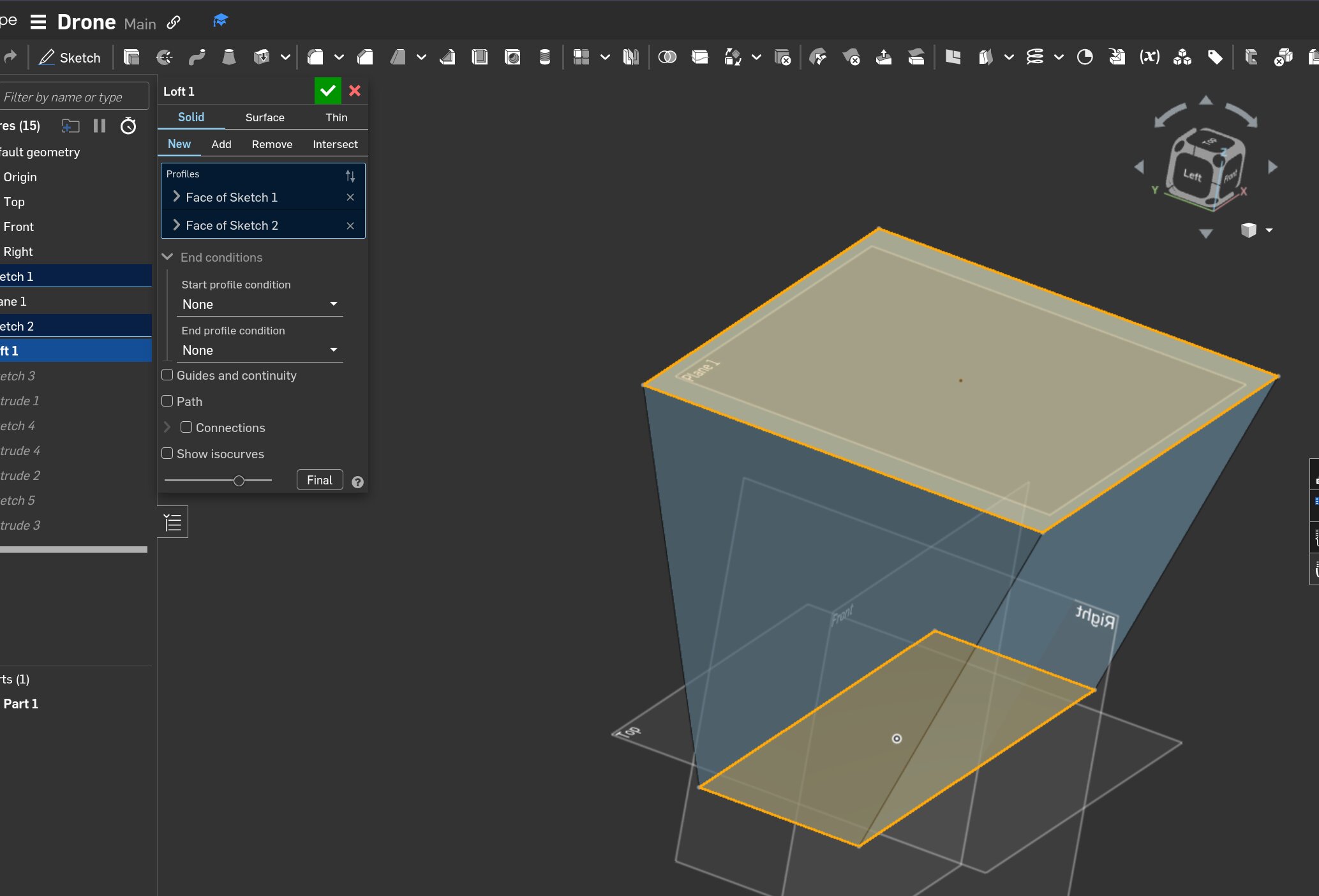
Loft creates a smooth solid body between 2 surfaces.
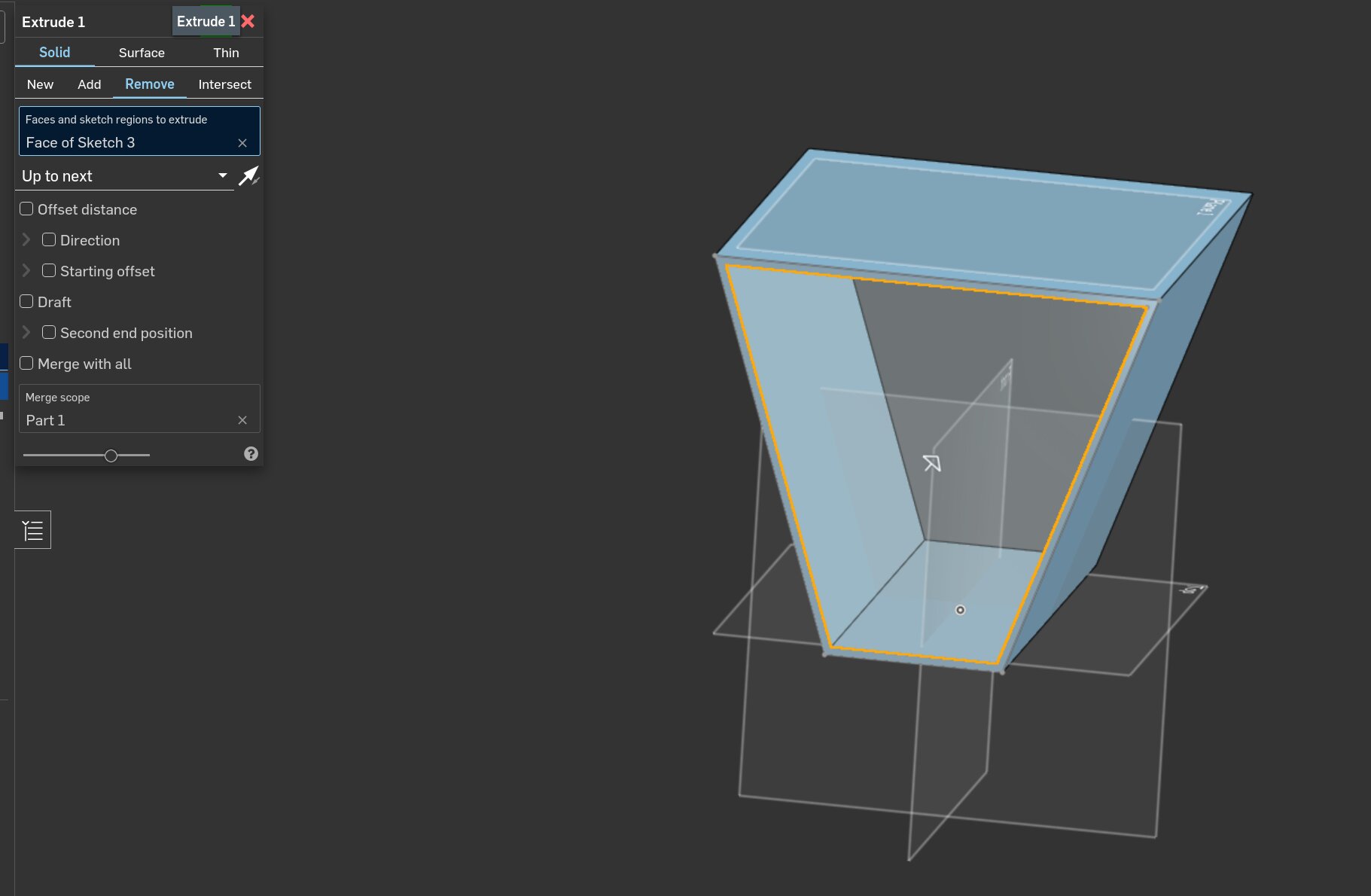 After that I created a sketch on the front surface with a offset so I could extrude the inside
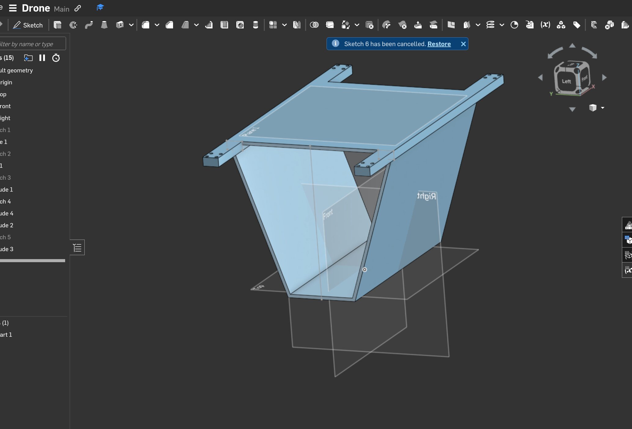 After that I sketched the motor arms and sketched holes on top to cut the holes.
Parameters
The parameter menu is very nice in Onshape It is on the side of the screen and it doesn't close automatically when modeling. Which is very nice.

Other notes
I think Onshape is a solid to fusion360 but the part that im missing is that I can instantly assign variables to anything. On another note Onshape is a lot nicer when working parametrically because you can slide the parameter menu on the side next to the design.
Blender
I wanted to make a render of the drone so I could visualize my idea to everyone. I don't have any experience with blender. The only experience i have is from the lecture we had.
Animating in blender
To learn animating I used this video.
Animating the rotors.
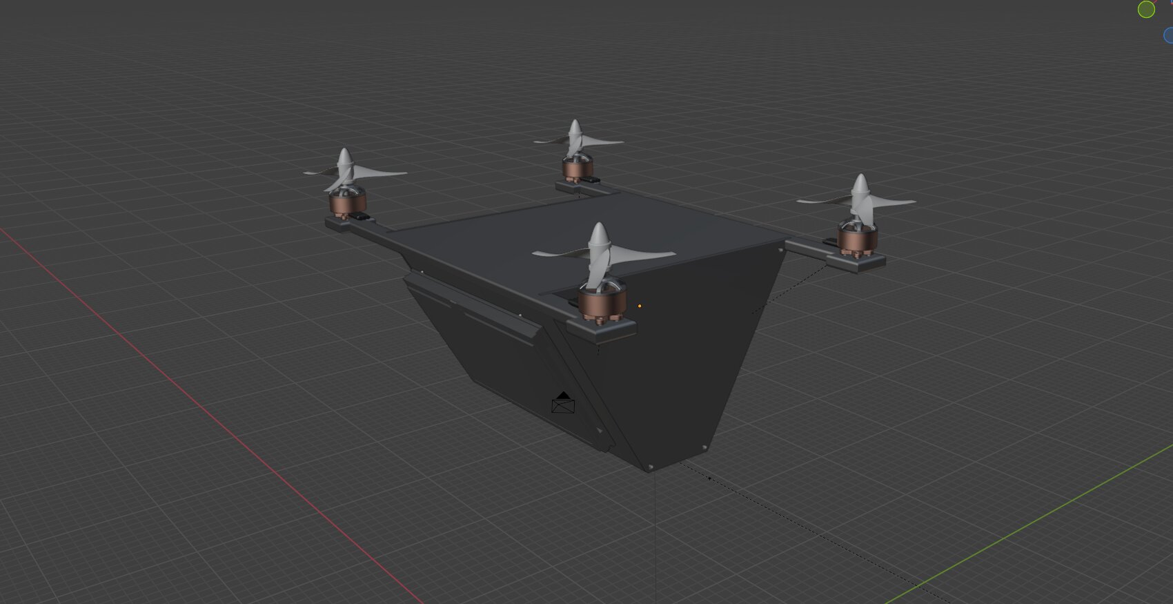
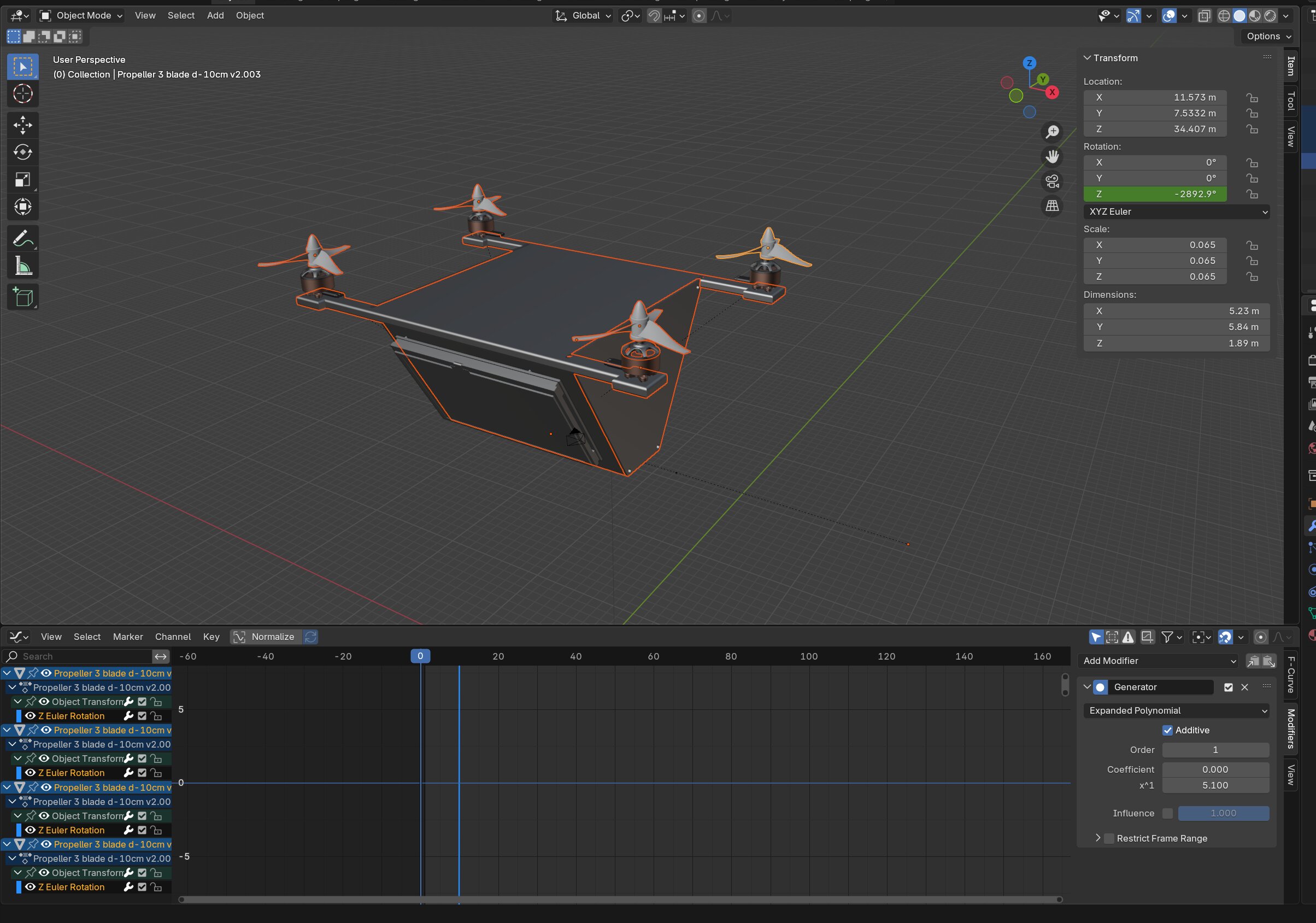
I have imported rotors from grabcad and aligned them on top of the motors. Using the G key. If you wanna grab something in blender you need to use G. The rest of the model I imported from fusion360.
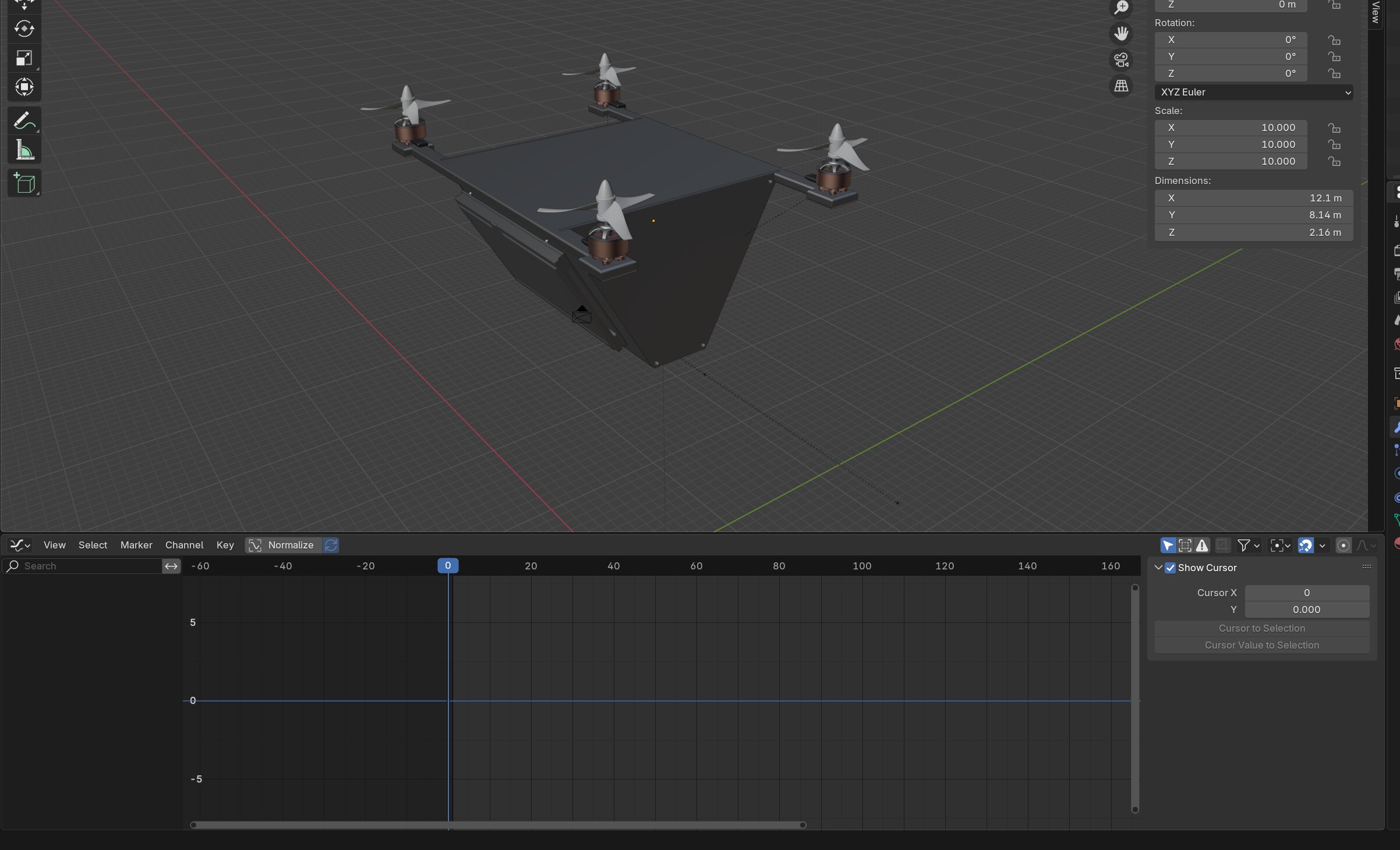
Then I opened the animation menu and pressed N to get the extended menu.
After that I selected all the rotors using shift click and pressed k to get to the keyframes menu.
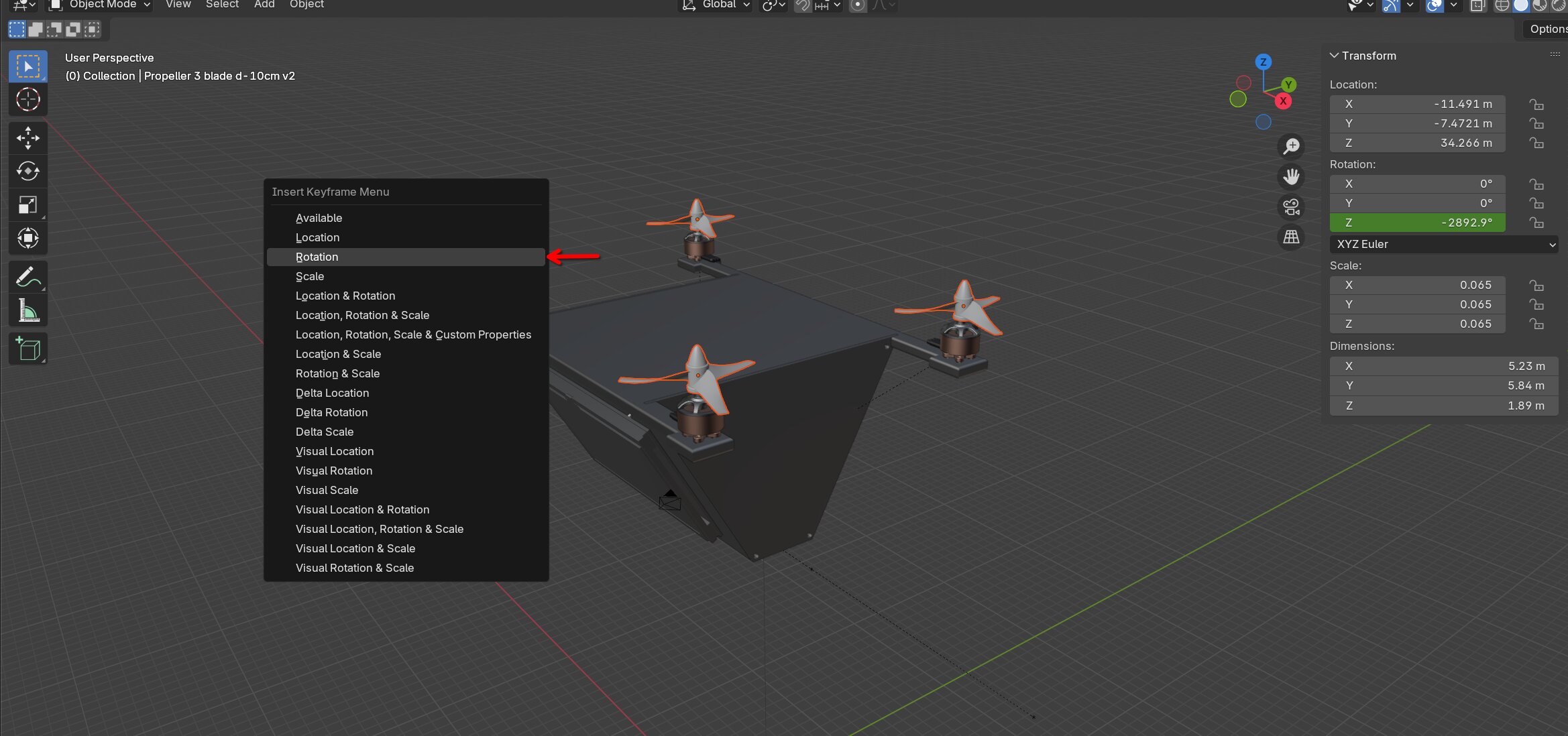
In there I selected the Rotation option to save that information inside the keyframes.
Then the Z Euler rotation should appear.
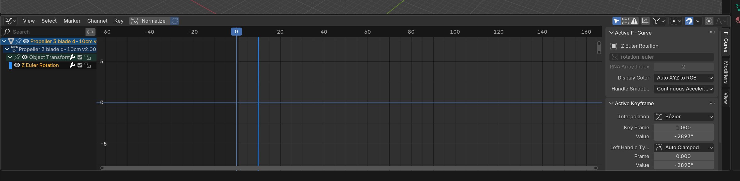
After clicking that I went into the modifiers menu and added a Generator and enabled additive. This makes sure that the Z angle only keeps going up. So it keeps spinning indefinitely.
After that you can select everything and press Control + L and then link animation data so all the propellors do the same. Then it should look like this. And if you press space they should start spinning.
Issue with rotor animation
When I try to angle the drone for an animation the rotors go spinning in a weird direction and I don't know why.
Quirks of the animation timeline
The keyframes only show up when you've selected the part/parts that have keyframes. Otherwise your timeline would be empty. Don't get confused by it.
Animating the drone
When animating the drone I ran into some issues. When adding keyframes my drone was flying away without it's propellors.
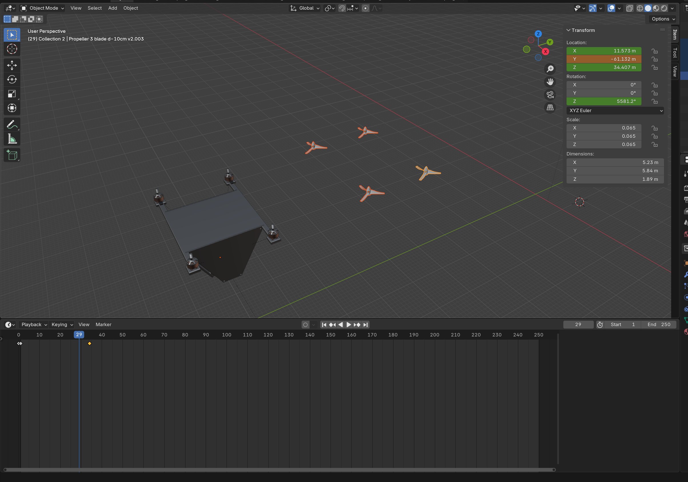
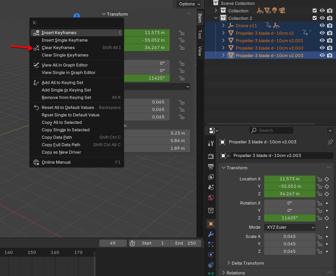 I fixed the issue by right clicking the location data in the Transform menu and clicking clear keyframes. Animating in blender is really straight forward. You move the objects and then press
 k and choose the keyframes that you wanna store.
Rendering in blender
Making a scene
The first thing I did is make a floor. I did that by placing a flat plane and scaling it by a lot so it covers the floor.
When you want to give objects textures or colors you need to assign materials to them. You can assign a material by going into the material tab on the bottom right.
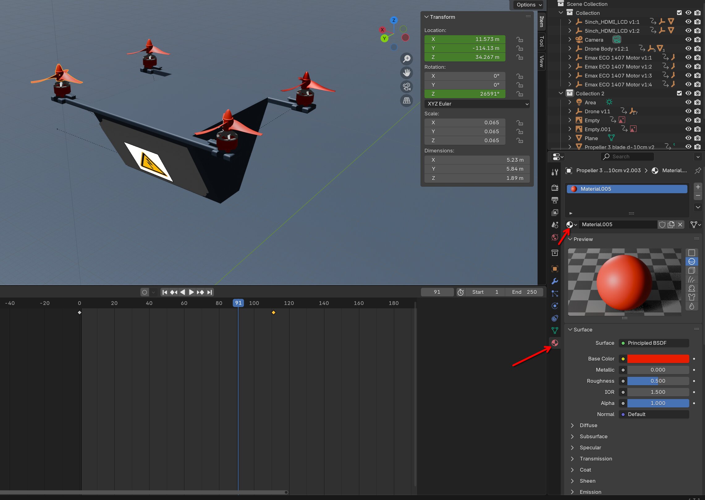 In there you can change colors and do all other sorts of fun things. If you press
 Z and then select render you can see the rendered project.
Rendering with images
I've struggled with rendering images. But I found out you can import images as materials and then they do get rendered. If you import it as image it doesn't get rendered in the 3d environment.
First you wanna go to the material and import the image into the material. When you the box next to base color a big menu appears with a lot of options.
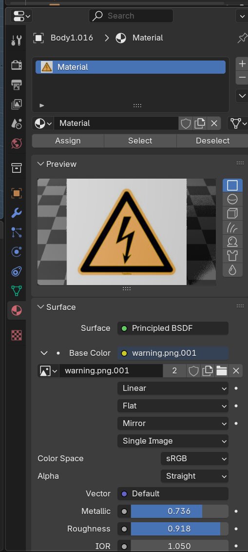
In the menu you wanna select image texture. When you've done that it will probably look something like this.
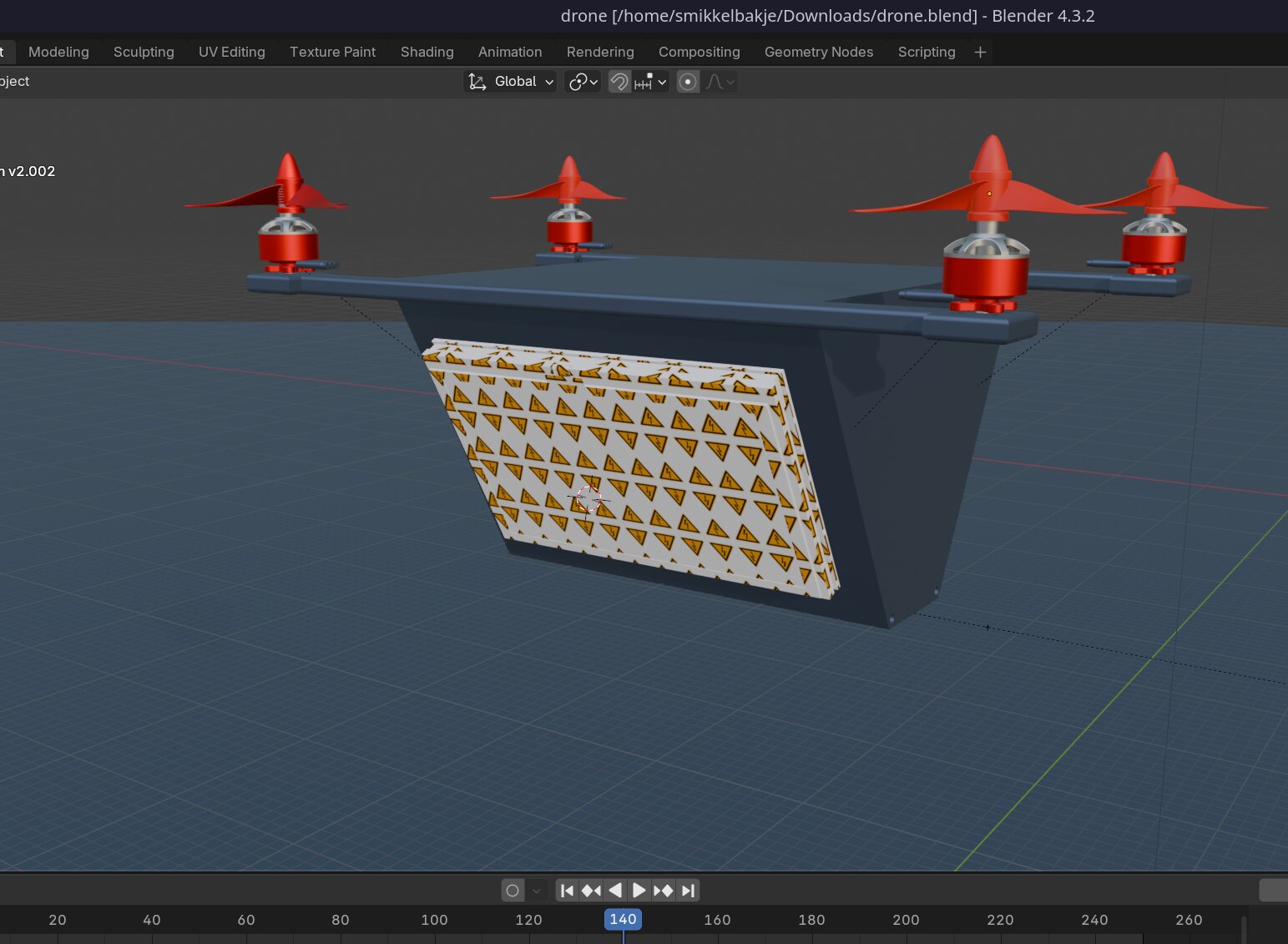
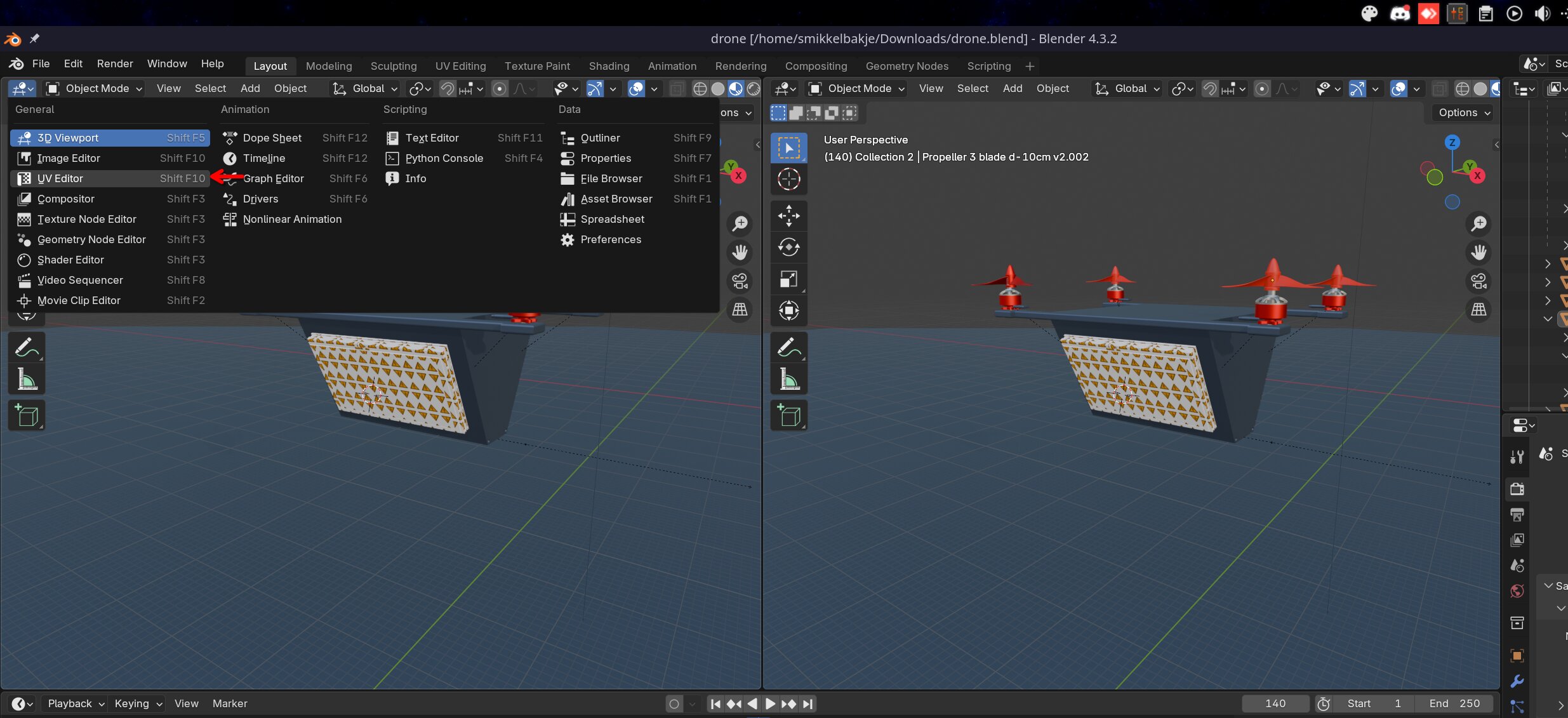
To fix this we need to do some UV-mapping? A UV-map is a way to tell blender how and where textures should be rendered. First start off creating a second view by dragging the top left corner of the 3d viewer to the middle. Then open the UV-editor using the top left button.
Then you can press the object you wanna edit on the right and edit it on the left. To get the object in the uv editor you need to select it and then press tab.
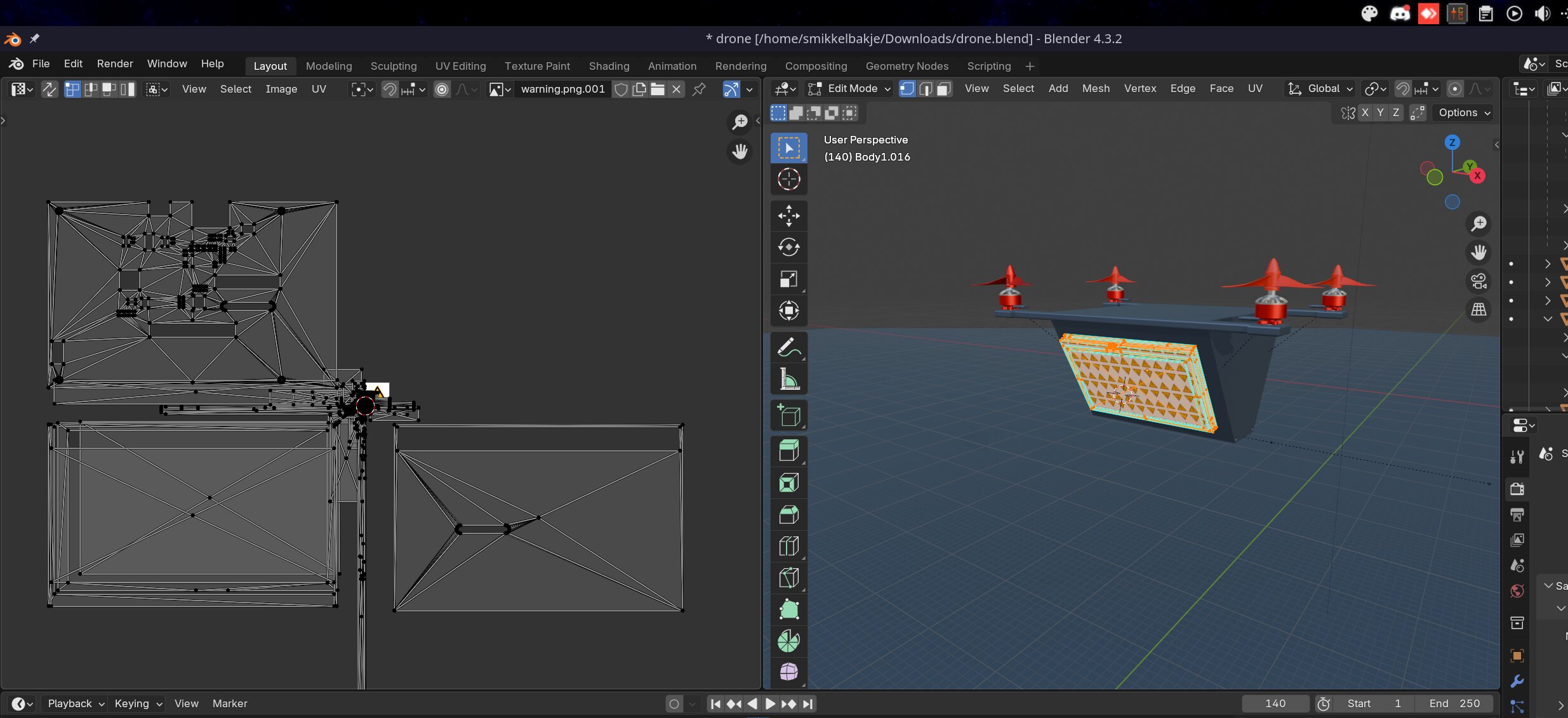
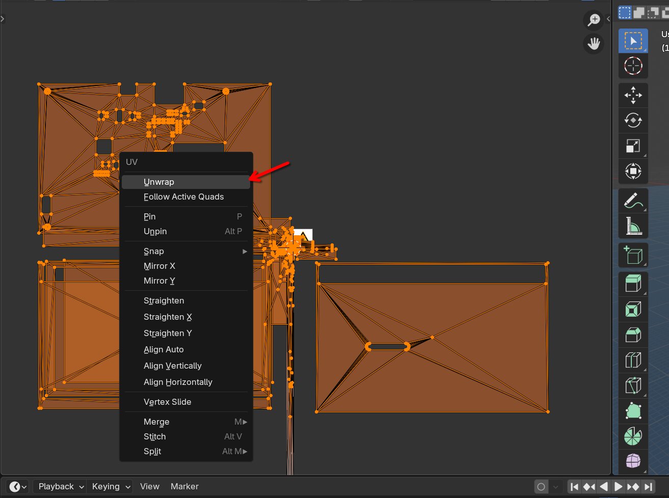
Then you will get something like this. Now drag over everything and press unwrap
 That will make everything disappear.
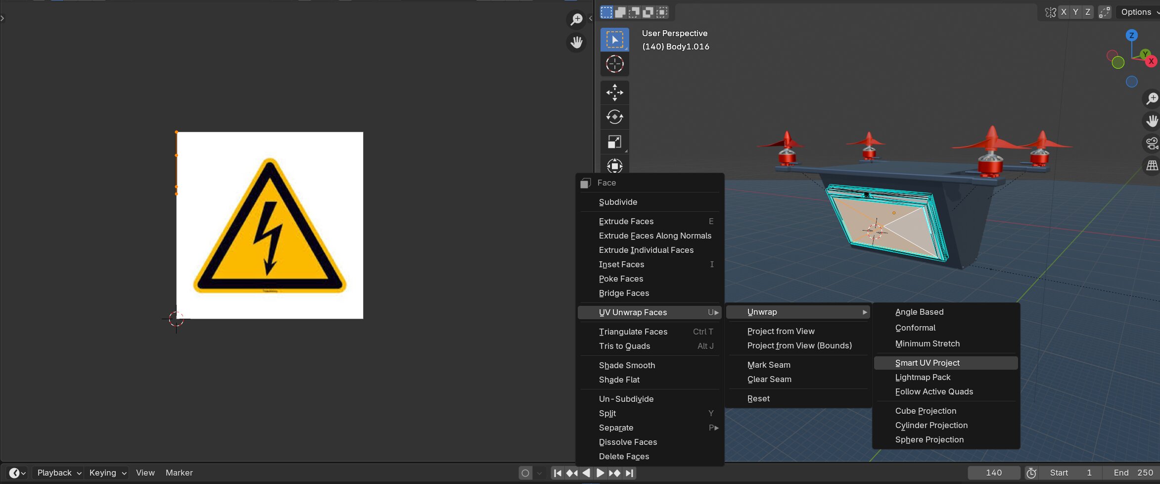 Now you can select faces in your 3d editor you want the image on. And right click and press
 UV unwrap faces -> Unwrap -> Smart UV project
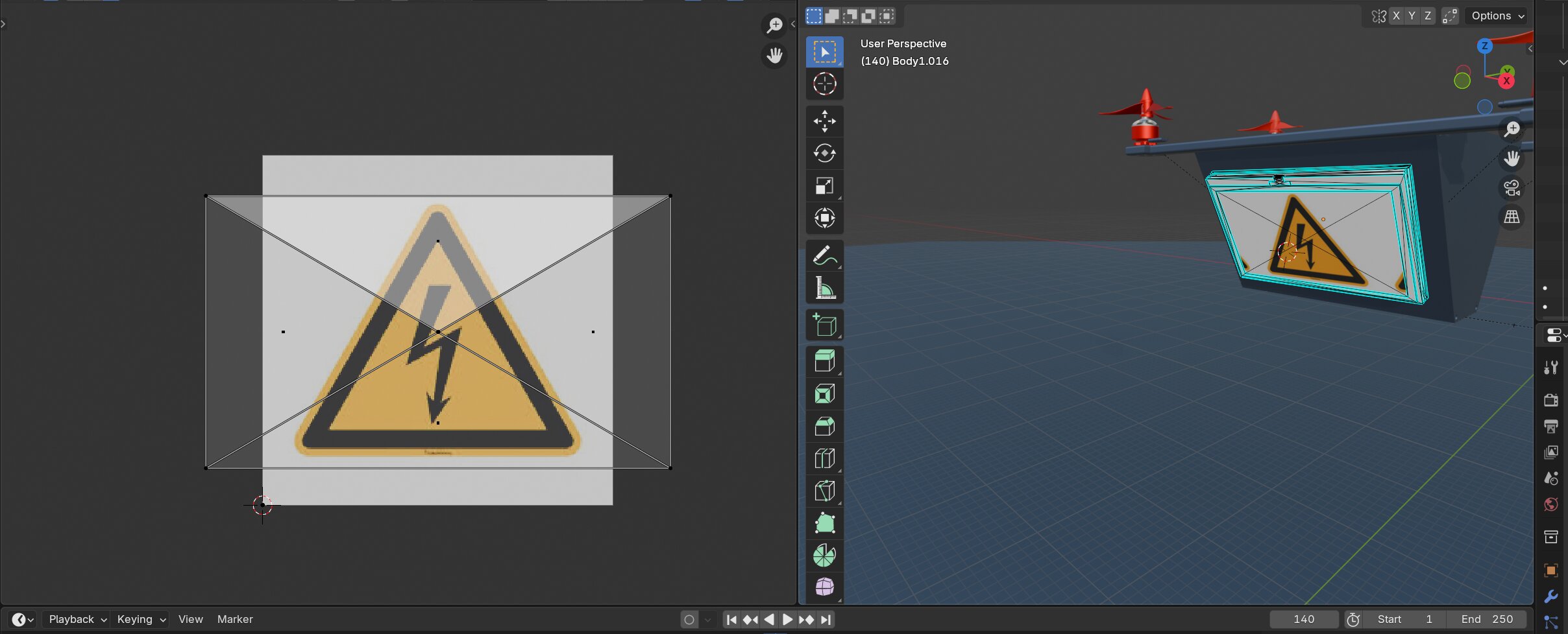
Now you have a couple of face on the image and you can see your changes directly reflect on the 3d model. 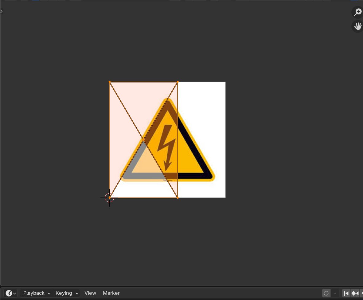
You can move and edit the faces around on the uv map using G R S.
Result:
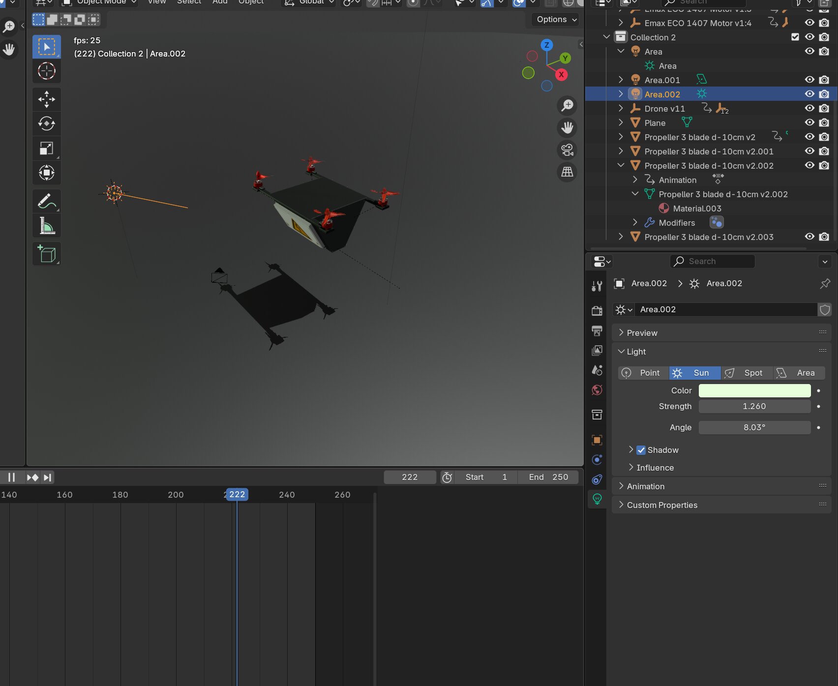
Setting the camera and lighting
For a render to look good the camera needs to be positioned well and there needs to be lights.
When in object mode you can move your cursor using shift + right click and then press shift + a to create a light. When you've created a light or selected one you can change the settings of the light. For now i've used Sun as light type because I couldn't get any other to work.
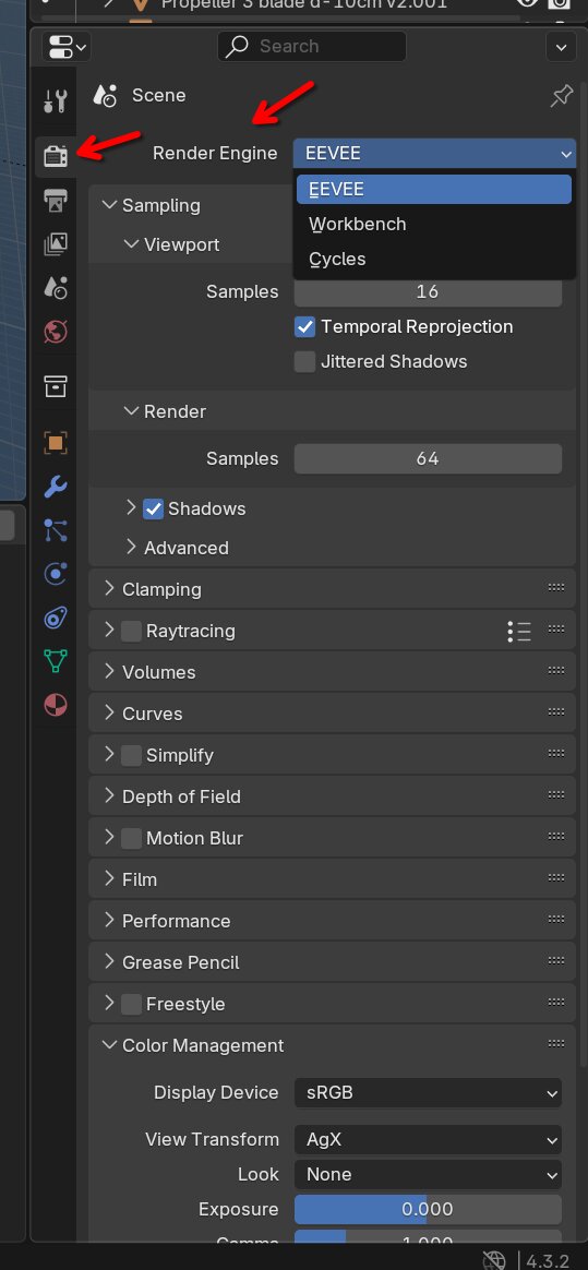
Rendering
To start rendering a video or image you first need to set the render settings. That can be found on the left bar at the tv icon. I was searching a lot to figure out where it was until I searched a video explaining that you can define the output location and type.
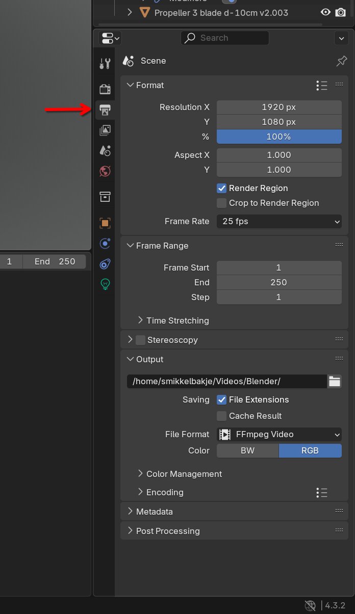
After that you need to set the output location and file type. That can be done in the menu right under the first menu. Otherwise your render will get saved in a random location.
In there you can change render settings for this project. There are multiple render engines. Eevee is the fastest but lowest quality and Cycles is the slowest and heaviest one but looks the nicest. Workbench is somewhere in between.
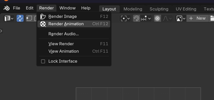
After setting all your settings you can go to the top menu and press render and choose if you wanna render an image or video.
Result:
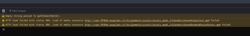
Issue with adding videos
When trying to view videos on the web my firefox says no MIME type.
I fixed it by searching basic video tag documentation. Then I added type="video/mp4" to every video tag. Because when pasting in images in markdown vscode forgets to add it.
source : https://www.w3schools.com/tags/tag_video.asp
What I also needed to do is set the absolute path instead of the relative path. For some reason it added Assignment in the link when trying to load the video
 Its supposed the be
 link.org/assets/video instead of link.org/assignment/assets. But for some unknown reason it changes it. The fix now is to set the absolute path starting with /assets/video.mp4 So now its referenced like this. ```html
instead of
```html
<video controls src="../../assets/assets_week_2/blender/droneRender.mp4" title="Title" type="video/mp4"></video>
Conclusion/My thoughts
I liked this week. I learned a lot about blender and OnShape at the start of the week I really hated Onshape because I didn't like how to camera feels and finding all the tools is frustrating but after a while I got comfortable with it and I liked some aspects of it. I also worked with Fusion360 also learned a couple of new things in there like the offset planes.